Compare all designs — interactive (every dot links to its card)
Every directional single-element antenna, gain vs a rear-rejection metric — top-right is best. Use the switch to set the x-axis: F/B is the classic front-to-back (all designs); F/worst-3D-lobe is the ratio to the worst lobe anywhere on the full sphere — the DF ambiguity headroom — reported by the four full-sphere-scanned designs (the CNC-cut family + a915_moxon). Hover a dot for its headline; click to open the card.
The monopulse Σ/Δ pairs: Σ beam gain vs the depth of the boresight Δ null (deeper null → sharper bearing). Ringed dots (†) feed through the real printed MIST rat-race coupler rather than an ideal in-sim one.
DF resolution (SRL) for every design on one graph — the closest two equal-power targets that stay tellable apart (GLRT, CFAR 5%, worst-case 5 dB interferer), vs SNR. Lower is sharper. Colour = element family; bold = Σ/Δ pair, thin = single antenna (beam-scan) — the pairs form the lower (better) band. Hover a line to isolate it and read its name; click to open the card. The two dashed guides are the −5 dB (harsh) and −15 dB (nominal) backgrounds.
Antennas
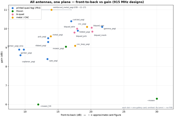
All antennas, one plane — joint F/B-vs-gain comparison
20 beam designs on one chart: front-to-back vs gain, colored by family (printed quasi-Yagi / Moxon / bi-quad / metal-CNC) · every dot is a gallery card below — values parsed LIVE from each card's headline (hand overrides where the card quotes a range, e.g. reinforced_metal_yagi F/B ~11–17) · ifa omitted (omni — no F/B) · headline figures only: boundaries/models vary per card (MUR vs PML, ideal vs localized drive), so treat cross-card deltas under ~0.5 dB as noise · regenerate any time with modal run compare_antennas.py — new cards join automatically
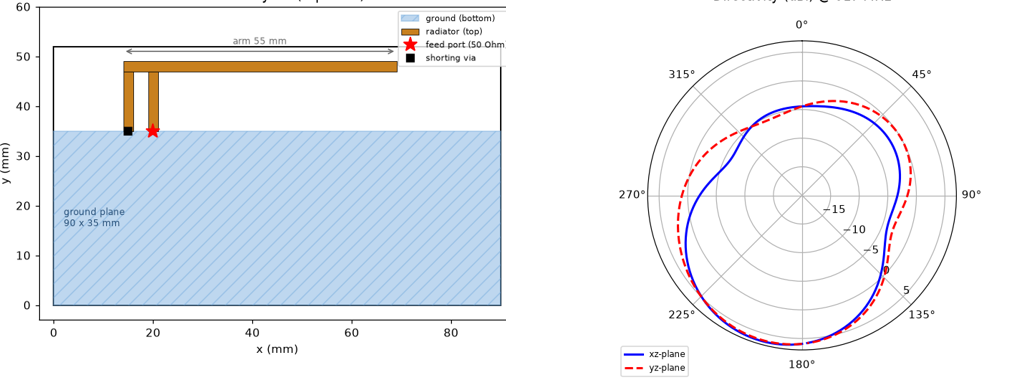
Inverted-F antenna (IFA)
916.7 MHz · S11 −11.9 dB · 6.4 dBi · BW 26.8 MHz · omni
⬗ stack-up: FR4 1.6 mm (εr 4.3) · 1 oz Cu (35 µm)
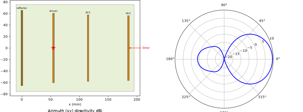
4-element PCB Yagi (skeletal FR4)
9.5 dBi · F/B 13.5 dB · S11 −15 dB · drone-light · F/worst-3D-lobe 13.5 dB
⬗ stack-up: FR4 1.6 mm (εr 4.3) · 1 oz Cu (35 µm) · skeletal
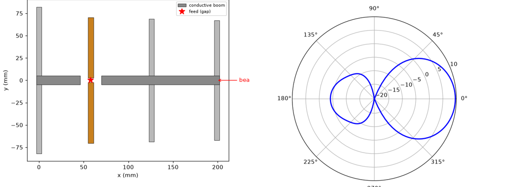
Machined Yagi (conductive boom)
9.6 dBi · F/B 13.9 dB · S11 −17.7 dB · free-space metal · F/worst-3D-lobe 11.7 dB
⬗ stack-up: machined metal · free-space (no substrate)
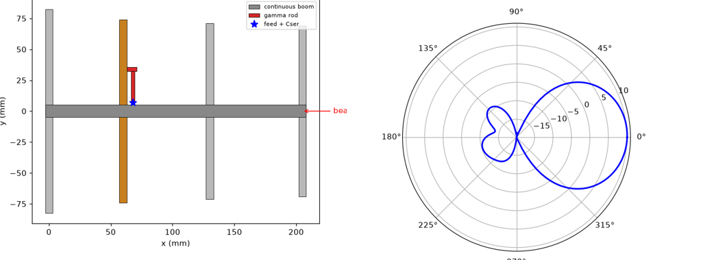
Single-piece gamma-matched Yagi
10.1 dBi · F/B 21.7 dB · S11 −22.9 dB · direct coax, no balun · F/worst-3D-lobe 12.1 dB
⬗ stack-up: single-piece machined metal · free-space (no substrate)
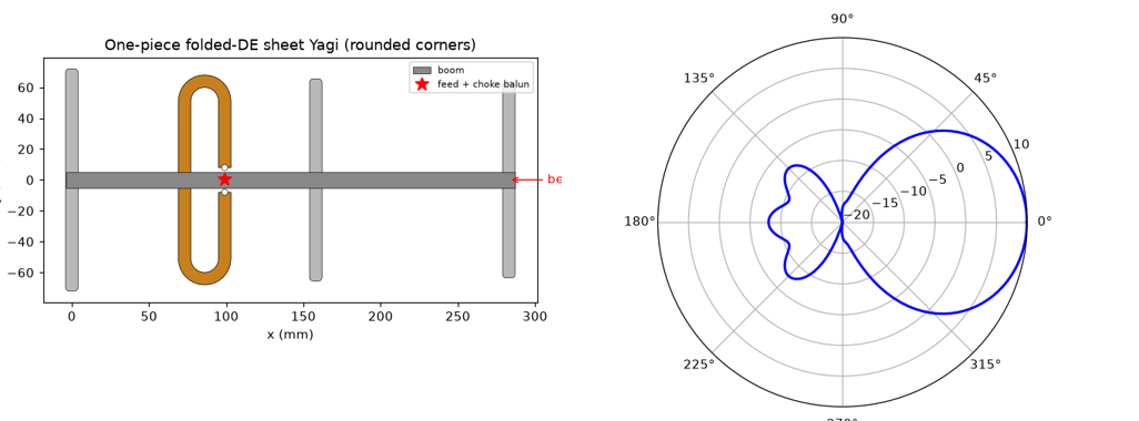
One-piece folded sheet Yagi (CNC)
9.9 dBi · F/B 18 dB · smooth driven · CNC DXF + M2 feed
⬗ stack-up: Al / brass sheet 1.0–1.5 mm · free-space (no substrate)
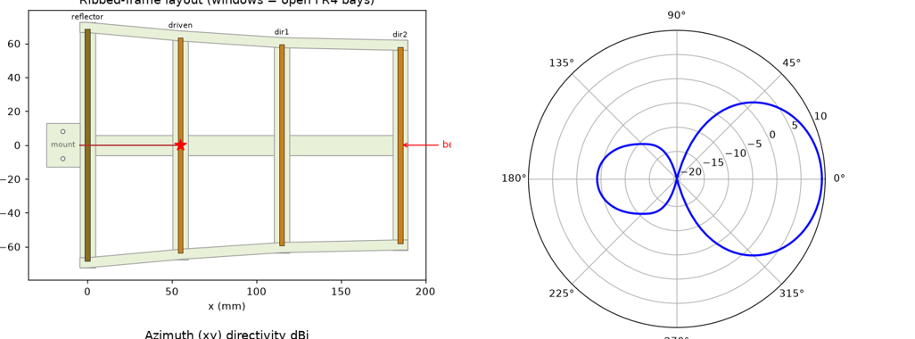
Ribbed-frame PCB Yagi (CNC FR4)
9.3 dBi · F/B 13.5 dB · S11 −14 dB · skeletal frame + tapered side ribs · F/worst-3D-lobe 13.5 dB
⬗ stack-up: FR4 1.6 mm (εr 4.3) · 1 oz Cu (35 µm) · ribbed frame
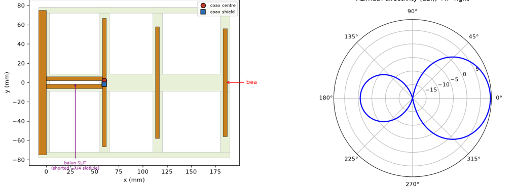
Single-layer coplanar quasi-Yagi (slot balun)
8.6 dBi directivity · 6.9 dBi realized (η 68%, FR4 loss) · F/B 9.3 dB · ribs-only FR4 · 4 mm slot cut through FR4 (air balun) · S11 −29 dB · Gerber · F/worst-3D-lobe 9.3 dB
⬗ stack-up: FR4 1.6 mm (εr 4.3) · 1 oz Cu (35 µm) · single top layer, ribbed
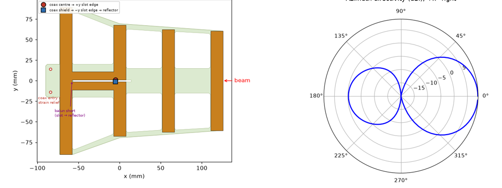
Coplanar quasi-Yagi — simulated from an uploaded Gerber set
8.9 dBi · F/B 9.1 dB · E-HPBW 58° · S11 −21.6 dB @915 (−34 dB @ res 903 MHz) · direct 50Ω, no matching network (Zin 47+j8) · simulated AS-DRAWN from the user's two gerber layers (top copper + FR4 outline) parsed with gerbonara into openEMS — copper as exact boxes, FR4 as the routed/flared frame · λ/4 slotline balun (slot shorted at the reflector) feeds the driven dipole; coax solders across the slot at the driven element (centre→+y arm, shield→−y arm→reflector) · reflector + 2 directors · 215×179 mm · F/worst-3D-lobe 9.1 dB
⬗ stack-up: FR4 1.6 mm (εr 4.3) · 1 oz Cu (35 µm) · single top copper layer · routed/flared FR4 frame (windows)
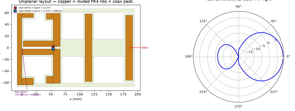
Moxon-reflector quasi-Yagi (manufacturing-robust fat elements)
9.05 dBi · F/B 16.2 dB, flat 14.9–16.2 across ±20 MHz detune · S11 −34.6 dB @915 (Zin 52+1j — direct 50Ω, no matching network; Re Zin flat ~52Ω over 0.8–1.0 GHz) · res 913 MHz · beats the fully-margined earlier version (8.4 dBi · F/B 15.0 · S11 −17.3) on every metric · directors HUG the copper (uploaded-gerber look, no FR4 apron) and are RE-TUNED +10 mm (126/122) to repay the lost dielectric loading — the driven (match) and reflector (Moxon null) keep 3 mm FR4 aprons · one CONTINUOUS central boom rib spans reflector → both directors; INCLINED side rails follow the element-tip envelope so every director ties into the frame at its own height · FAT low-Q copper (driven/directors 12 mm, feed strips 10 mm, Moxon tips 12 mm) · l_drv 120, tip_x 20, gap C 22 · director length sits 4+ mm below the parasitic-resonance rollover (still F/B 15.1 at +14) · slotline balun, coax solder pads (centre→+y arm, shield→−y arm→reflector) · Gerber + STEP + DXF (CST Studio 2024-ready: import the STEP as solids, or the layered DXF — COPPER/BOARD/DRILL — and extrude; zip README has the steps + port placement)
⬗ stack-up: FR4 1.6 mm (εr 4.3) · 1 oz Cu (35 µm) · single top layer · CNC-routed: continuous boom + inclined rails, directors hug the copper
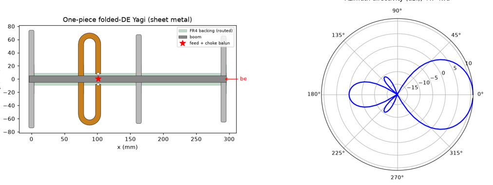
FR4-reinforced sheet-metal folded Yagi
~11 dBi directivity · F/B ~11–17 dB · CNC sheet metal in AIR + FR4 backing ROUTED to low-E regions (boom spine + parasitic-centre tabs) · verified: RF essentially unaffected by FR4 placement (full board ≈ spine ≈ parasitic tabs) · low-R folded feed: choke balun + ~9 pF series-cap trimmer (VSWR ~2.5)
⬗ stack-up: CNC sheet metal (in air) + routed FR4 backing (εr 4.3 · 1.6 mm) at low-field regions only
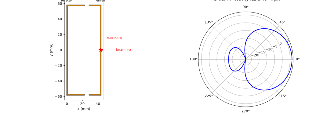
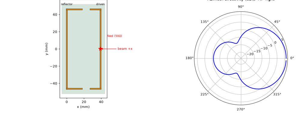
Moxon rectangle (deep rear null)
6.3 dBi · F/B ~30 dB (deep null, PML) · direct ~50Ω (56−j9, S11 −20 dB) · 44×117 mm (0.13λ×0.36λ) · published Cebik/AC6LA dims · 1.5 mm trace · 1:1 choke balun · F/worst-3D-lobe 5.1 dB
⬗ stack-up: 1.5 mm trace · 1 mm sheet metal/wire · free-space (no substrate)
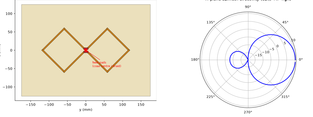
Moxon rectangle on FR4 (retuned gap)
6.0 dBi D · 5.2 dBi realized (η 82%) · F/B ~12 dB — FR4 loss caps the deep null · direct 50Ω (47−j5, S11 −24 dB) · gap widened to 8.8 mm · 39×94 mm · choke balun
⬗ stack-up: FR4 1.6 mm (εr 4.3) · 1 oz Cu (35 µm) · single top layer
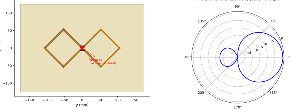
Kharchenko bi-quad, wired (metallized-FR4 reflector)
10.0 dBi (PML) · F/B 17.9 dB · S11 −33 dB @ 915 · Zin 49+j2 Ω — DIRECT 50 Ω, no matching network · BW(−10 dB) 86 MHz · HPBW 58° · side 83 mm, spacing 46 mm (0.14λ, sets R: +1.7 Ω/mm) · reflector 350×250 copper-clad FR4 · 2 mm Cu wire bent from ONE 680 mm piece (bottom centre = continuous bend, ends meet at top pad) · braid collar bonded 360° to plate + 5-bead ferrite choke (balun) · solder pads, bending template DXF · CM check (explicit coax): bare −27.5 dB / collar bond −61 dB / λ/4 sleeve −49 dB @915 — the reflector bond IS the balun workhorse · WIND→FEM (OpenFOAM RANS + CalculiX): Cd 1.23, 59 N @30 m/s (133 N @45) · 1.6 mm plate on a 40×40 mm centre clamp bows 11 mm at the corners @30 m/s → Δspacing ≈2.2 mm → ΔR +3.7 Ω, Δf −0.7 MHz — match holds (linear FEM, conservative) · σvM 27 MPa (≈16× FR4 margin) · @45 m/s corners flap ~25 mm — use a full-width mast plate / 3 mm substrate for permanent outdoor mounts · FUSELAGE MOUNT (fixed-wing, vertical, flow along the 350 mm side): cruise drag only 0.6-0.7 N @30 m/s · sideslip turns it into a fin: |Fy| 20 N @β=10° / 27 N @β=15°, mount moment 3.4 N·m · plate bows 5.1 mm @β=15° → ΔR +1.7 Ω — RF-benign · beam points sideways; reflector shields the airframe · F/worst-3D-lobe 17.0 dB
⬗ stack-up: 2 mm solid Cu wire element in air · reflector: single-side copper-clad FR4 1.6 mm, 350×250 mm
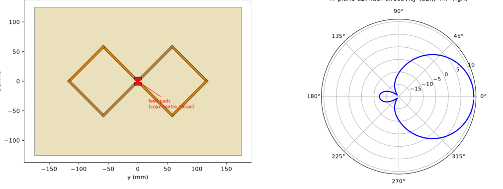
Kharchenko bi-quad, PCB (etched FR4 + metallized-FR4 reflector)
9.8 dBi D (PML) · ~9.7 dBi realized @ η 97% · F/B 17.5 dB · S11 −28 dB @ 915.0 · BW(−10 dB) 88 MHz · side 75 mm — FR4 loading shrink 0.90 measured by sweep (settles the 0.80-vs-0.92 dispute) · same 46 mm spacing/standoffs as the wired build · copper faces the reflector: coax pads solder directly, no vias · braid collar to plate + ferrite choke · element board 232×126, nylon M3 standoffs · CM check (explicit coax): bare −27.5 dB / collar bond −61 dB / λ/4 sleeve −49 dB @915 — the reflector bond IS the balun workhorse · WIND→FEM (OpenFOAM RANS + CalculiX): Cd 1.23, 59 N @30 m/s (133 N @45) · 1.6 mm plate on a 40×40 mm centre clamp bows 11 mm at the corners @30 m/s → Δspacing ≈2.2 mm → ΔR +3.7 Ω, Δf −0.7 MHz — match holds (linear FEM, conservative) · σvM 27 MPa (≈16× FR4 margin) · @45 m/s corners flap ~25 mm — use a full-width mast plate / 3 mm substrate for permanent outdoor mounts · FUSELAGE MOUNT (fixed-wing, vertical, flow along the 350 mm side): cruise drag only 0.6-0.7 N @30 m/s · sideslip turns it into a fin: |Fy| 20 N @β=10° / 27 N @β=15°, mount moment 3.4 N·m · plate bows 5.1 mm @β=15° → ΔR +1.7 Ω — RF-benign · beam points sideways; reflector shields the airframe · F/worst-3D-lobe 16.0 dB
⬗ stack-up: element: FR4 1.6 mm (εr 4.3) · 1 oz Cu, single layer · reflector: copper-clad FR4 350×250 mm · 46 mm air gap
Kharchenko bi-quad V3 — wire-MESH reflector (min drag)
MESH PITCH 40 mm (0.12λ) is the largest within 1 dB of solid — PML: 9.85 dBi (−0.19 dB vs solid) · F/B 20.2 dB (+2.3 dB BETTER — pitch scan: p20 −0.10 dB, p30 −0.25, p40 −0.47 MUR, p60 −1.09 FAILS) · retuned: side 82.3, spacing 38 (mesh raises feed R; spacing pulls it back) → S11 −36.6 dB @915, Zin 48.6−j0.3, BW 88 MHz · element = same 2 mm Cu wire bi-quad · STABLE GAUGE (CalculiX beam-grid FEM, welded joints): pure grid on a centre mast is FLOPPY (Ø4 wire → 8.8 mm @45 m/s); with Ø8 frame+spine-cross rods ALL gauges hold ~2 mm — pick Ø2 mm wire (1.9 mm defl, 5 MPa; thicker wire is WORSE: drag grows faster than stiffness helps) · the spine cross also helps RF (restores the centre image plane: Zin 55→49 Ω, F/B +2 dB) · DRAG (lattice member-sum, EN 1993-3-1 style; direct CFD under-resolves 3 mm wires): solidity 0.19 → frontal 10.8 N @30 m/s = 5.5× LESS than solid (59 N), 45° 6.4 N, edge-on 5.8 N (CORRECTED: every vertical member is a crossflow cylinder at any panel yaw — an early leading-rod-only figure of 1.3 N undercounted; note the SOLID plate is actually lower-drag edge-on, 0.6 N), survival 24 N @45 m/s · same coax feed: collar bond to the 40×40 centre patch + ferrite choke · CORRUGATION STUDY (asked: corrugate instead of spines — REJECTED, spine cross wins both ways): box folds along z, ±d/2, period 2×pitch · STRUCTURE: corrugation stiffens the panel FIELD but not the LOAD PATH to the point clamp — corr d20+frame alone 20.2 mm @45 m/s (vs 1.9 mm spine cross); best hybrid (corrugation replaces only the HORIZONTAL rod, vertical Z-rod kept) 3.9 mm — still 2× worse · RF: gain survives (−0.15 dB) but the periodic folds diffract backward: F/B 22.3→16.5 dB (−5.9) at d20, −8 dB at d28, plus Zin drift · also harder to fabricate than two straight welded rods · F/worst-3D-lobe 16.6 dB
⬗ stack-up: 2 mm Cu wire element · reflector: welded steel wire grid Ø2 @ 40 mm pitch, Ø8 frame + spine cross, 350×250 mm, 40×40 solid centre patch
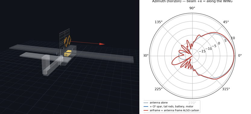
Bi-quad V3 on a 1.6 m FPV plane (Ranger 1600) — carbon vs pattern
V3 mesh bi-quad vertical on the fuselage deck of a Volantex Ranger 1600 (1.6 m span, 1.1 m EPO fuselage, 1050 g AUW), plate edge-on to flight, beam along the wing · EPO foam is RF-transparent — modelled the CONDUCTORS: Ø8 CF wing spar (runs ALONG THE BEAM 40 mm below the frame), 2× CF tail rods, LiPo, pusher motor (openEMS PML, 16M cells) · EFFECT: main lobe unchanged (fwd 9.85→10.06 dBi, +0.2), F/B 20.1→21.3, match unchanged — the damage is back/side RIPPLE (±2-3 dB scalloping −5..−15 dB region) from spar scattering · antenna frame built from CARBON tube instead of steel: Δpattern < 0.09 dB everywhere (CF skin depth 0.1 mm @915 = good conductor) → frame+spine in CF solves the mass problem: Ø8 steel 0.71 kg → CF 0.04 kg; whole antenna ~160 g with Ø2 alu mesh wires (~15% AUW) · FLIGHT-TIME COST (member-sum drag + induced-drag-of-mass, 3S 5 Ah, cruise 12 m/s, clean endurance 77 min): ground-spec mesh 1.07 N → 39 min (−49%!); flight-spec (Ø1.5 wires, Ø5 CF frame, no spine — deck mount doesn't need the mast stiffening) 0.66 N → 49 min (−37%); + rod fairings 0.50 N → 52 min; 0.5 mm alu sheet posts 56 min BUT FAILS the β=15° gust check (t³ stiffness: 9.5× floppier than FR4 1.6 → ~17 mm corner flap @18 m/s, flutter risk, and no solderable face for the collar bond) · RECOMMENDED AIRBORNE BUILD: the original 1.6 mm metallized-FR4 plate edge-on — 0.27 N, 51 min (−34%), 1.8 mm @β=15° gust, solderable copper, proven V1 tuning · edge-on flight still INVERTS mesh-vs-solid drag (vertical mesh wires are crossflow cylinders at any yaw; a plate shows only its 3 mm edge) · flight-mesh (Ø1.5/Ø5 CF) = 49 min with 5× lower gust loads if rough air dominates · mount over the CG, beam points sideways — reflector shields the airframe · ROTATING 3D MODEL embedded below (drag to orbit) · EMITTER for flight: the wired element resonates ~180 Hz on its centre stub — inside the pusher-prop band (133–200 Hz @ 8–12k RPM, prop 20 cm behind) → solder-joint fatigue risk; use the PCB emitter: 0.8 mm FR4 board (43 g vs 108 g @1.6 mm), retuned side 78 @ spacing 46 → S11 −31 dB @917, realized 10.27 dBi (η 98% — thinner FR4 is LOWER loss), centre coax bond acts as 5th support lifting board modes above the prop band · SPACERS: keep NYLON standoffs deliberately — axial (spacing) mode ~550 Hz (RF dim rock-solid), lateral sway ~25–40 Hz = vibration ISOLATION below the prop band; aluminium/steel standoffs land AT 125–190 Hz, inside it · nyloc hardware (nylon posts loosen), optional teardrop fairings halve the ~0.11 N spacer drag · MOTOR-SYSTEM FOLLOW-UP (the motor BODY was always in the sim — a PEC block at the pod rear; now added the conductors around it): WIRING HARNESS (batt leads/ESC/phase wires, 25 cm strip) — negligible: main lobe +0.01 dBi, worst rear-az change 0.6 dB · PROP BLADES (8" CF, worst-case static orientations vertical vs horizontal bound the spinning-blade modulation): main-lobe ripple ±0.07 dB, rear lobes up to ±1.7 dB at 2×rev-rate (~270-400 Hz sidebands, −20 dB region only), S11 swings −20.3↔−21.0 dB — the link never sees it; a metal-hub/alu prop would double the ripple, keep CF
⬗ stack-up: V3 mesh reflector (Ø2 wires @40 mm, CF Ø8 frame+spine) · 2 mm Cu element · Ranger-1600-class EPO airframe
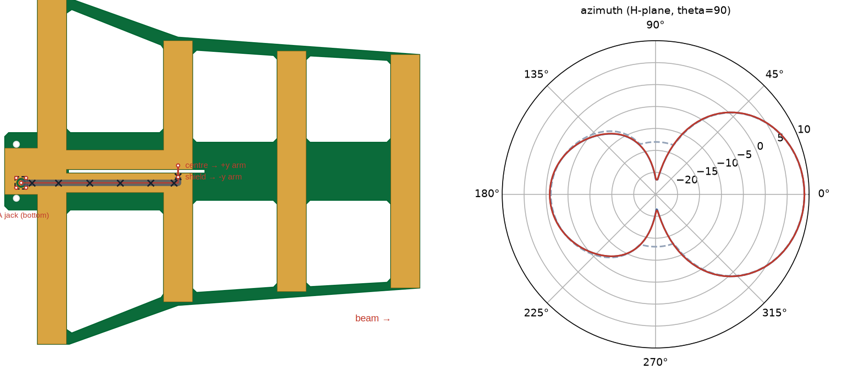
Gerber'd quasi-Yagi — SMA on PCB (rear tab or emitter) / pigtail (stand-mount)
8.9 dBi · F/B 9.8 dB · S11 -26.1 dB @915 (res 908 MHz wide-port model; AS-BUILT the localized-drive model puts the untrimmed board at ~892 MHz — apply the 1.7 mm/tip trim in the tables below to centre 915.0 at S11 -30.5 dB) · SMA ON THE PCB — REAL LIBRARY PART, not invented: Amphenol 132134 4-post flange jack (KiCad packages3D STEP, measured 6.35 mm sq × 9.55; official KiCad footprint drills: pin 1.5, posts 1.7 on a 5.08 mm square) on the BOTTOM of the rear FR4 tab at (−23.5, −6) — deliberately OFF the tab centre, the pin sits dead in line with the y=−6 return-strip run so the stiff jumper needs ZERO on-board bends — pointing DOWN along the vertical-ish stand that clamps the reflector centre, so the cable takes a straight plug and zip-ties down the stand, exiting in the pattern's rear null · RG-402 semi-rigid jumper (0.141", Ø3.58, ~82 mm — min bend r ~8 mm, which is exactly why the connector moved to the run line instead of the cable jogging to it) flat on the top face in ONE STRAIGHT RUN: centre → Ø3 pin pad (Ø5 keepout), shield seam-tacked along the tab GROUND POUR (bonded to the reflector at x=−15) → reflector → return strip → −y arm base; at the emitter the centre jumps the 2 mm slot to the +y arm pad — FEED POINT AND 58 mm SLIT BALUN UNCHANGED from the gerber_yagi element · FDTD A/B (PML_8, port at the emitter as always): bare 8.87 dBi / F/B 10.0 / res 902 → +SMA hardware 8.94 / 9.8 / 908 → +λ/2 CABLE down the stand 8.93 / 9.8 / 908 — the connector nudges resonance toward 915 and the cable then changes nothing (ΔS11 0.1 dB): the offset rear-tab position is just as field-quiet as the old centred one and the design stays CABLE-INDEPENDENT (the common-mode check the slit balun must pass) · modelled: real-size body + post blades + jumper EXTERIOR as bonded metal (the jumper interior is 50 Ω coax by construction); worst-case cable = bare λ/2 rod off the connector · MUR sanity A/B agrees · tab strain holes (−26, ±14) kept for a backup zip-tie · single element for a stand mount; the Σ/Δ finder pair can adopt the same rear-tab SMA per board · Gerber set parses clean (gerbonara) · 3D: STEP assembly (cadquery/OpenCASCADE — board, copper, the KiCad library connector, RG-402 swept along the route, now a single straight segment; CST/Onshape-ready) + interactive rotating 3D (three.js, real tessellated connector) with the stand/cable context · PIGTAIL ALTERNATE BUILD (second Gerber set, no board connector): the same RG-402 run, instead of landing on a pin pad, BENDS DOWN (r≥8) THROUGH A Ø6.5 EXIT HOLE at the pin-axis spot (−23.5, −6) — on the run line, so this quarter-bend is the cable's ONLY bend — and continues as a CAPTIVE pigtail down the stand; the tab pour is SOLID and the shield is soldered all around the hole rim (ground bond + strain relief); connector only at the far radio end · FDTD (PML_8): pigtail 8.95 dBi / F/B 9.8 / res 908 / S11 -26.4 dB @915 vs bare 8.87 / 10.0 / 902 — same behaviour as the SMA build (the exit is the same field-quiet spot); trade-off: ~0.05–0.1 dB less loss and no connector cost/height, but re-cabling means desoldering · DIRECT-SOLDER SMA AT THE EMITTER (third build, third Gerber set — no jumper at all): the same Amphenol 132134 vertical jack on the BOTTOM face right at the feed, offset to (58, +0.5) so the Ø2.2 pin pad bridges the slot into the +y arm (0.4 mm fab-safe gap), the two −y posts ground on the −y arm (= the shield bond), the two +y posts sit on ISOLATED ring pads; an FR4 BRIDGE stays in the routed slit (x 52–64) and the outline bumps to ±72.5 over the driven element · footprint survey (KiCad Connector_Coaxial, all families): every THT SMA uses the same pin+4-post ±2.54 square and every edge/SMT family is GSG — no standard layout suits a coplanar 2 mm slot, so the offset recipe is the practical optimum · the jack body under the feed is NOT free (unlike the field-quiet rear tab): it detunes ~+30 MHz and raises the feed R to ~61 Ω → driven RETUNED l_drv 135.4→140 (swept 139–145, MUR + PML; tuned on S11@915 — the S11 curve is double-dipped so the argmin 'resonance' readout hops between dips) · FDTD (PML_8) @915: jack 8.85 dBi / F/B 9.8 / S11 -17.9 dB; +λ/2 cable STRAIGHT DOWN 8.76 / 9.6 / -18.5 dB (VSWR ≈ 1.27, Zin 61−7j — matched a shade shallower than the rear builds' −29 dB; that residual is the body's R-shift, a documented property of feeding at the emitter) — cable-independent ONLY for the vertical exit (a parallel-to-board run re-tunes −12 MHz and follows cable dressing; see the routing study) · cable: straight plug, drop ≥60 mm, then over to the stand
⬗ stack-up: FR4 1.6 mm (εr 4.3) · 1 oz Cu (35 µm) · single top layer, uploaded-set outline (routed windows + balun slit) · Amphenol 132134 SMA jack (KiCad footprint), bottom face, offset to the y=−6 run line · RG-402 jumper, one straight run
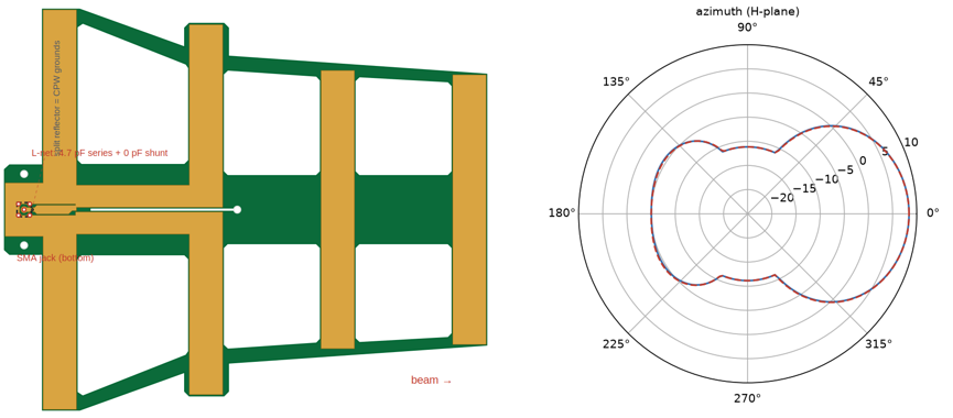
CPW-fed quasi-Yagi — rear-fed, single layer, smooth one-part-match feed route (new antenna)
915 MHz · SHIP v2 (no bay, ONE-part match, smooth route) — PML_8 @915 with the λ/2 cable: 8.40 dBi · F/B 13.4 dB · S11 -15.4 dB (Zin 36+3j); λ/4 cable identical: 8.40 / 13.4 / -15.4; MUR rod gate 82/164/246 mm: −16.1/−15.5/−15.6 dB, Zin pinned 42+13j — CABLE-INTEGRATED, the coax down the stand is the designed counterpoise and its length stops mattering · −10 dB band 866–984 MHz · board 216 × 180, FR4 1.6 · THE MATCH IS ONE PART: series 4.7 pF NP0 0402 across a 0.5 mm gap IN THE NECK right at the SMA pad, on MASK-DEFINED 0.65×0.7 mm lands (1005-metric pattern, 0.25 mm termination overlap per side — the manufacturing review caught the old 1.0 mm gap leaving the 1.0 mm part tip-to-tip with zero land; the honest pad geometry costs ~3 dB of match vs that unbuildable layout and is re-verified end-to-end), plus copper only — l_drv 166 is the X-trim, C re-picked 5.6→4.7 for the 0.5-gap fringing (the flare ribs conform to the tips at ±83.5, 0.5 mm routing margin) · SMOOTH ROUTE (three user-driven rounds, every step FDTD-measured): footprint drawn like a pad library — ROUND Ø3.0 pin pad (1.5 drill, 0.75 ring), 2.0 mm neck broken by the C gap, symmetric channel pad, ONE 45° taper to 4 mm, straight run, then a smooth 45° RAMP of the trace's lower edge into the bond (the old right-angle staircase is gone) while the ground edge runs dead straight to the slot mouth — the widening gap between them forms the junction POCKET · WHY THE POCKET STAYS (the negative results that shaped it): raising the whole feed axis +1.5 mm so the lower gap runs straight into the CPS slot looks cleanest but DELETES the pocket — the pad R collapses to ~25 Ω, a single series C saturates at ~−11 dB, and only a two-part L-network (8.2+3.3 pF, measured −27.4 MUR / −18.4 PML) can match it; a parallel ground ramp does the same; the C's position is a one-way street (R falls 36→15 Ω moving pad→bond, so the gap belongs AT the pad — moving it 3 mm downstream during the footprint redesign silently cost 5 dB); tie −26 vs −28 measures IDENTICAL on every new route (the loop-length lever died with the old jog) · v3 — FULLY PRINTED VARIANT (no SMD): folded driven element (fold 4 @ 6 mm gap, tip links 6, l_drv 160, Guertler step-up ≈2.33) on its OWN best-measured route — the RAISED AXIS (+1.5 mm, trace bottom at the transition height, lower gap straight into the slot, no pocket — nothing to feed a C into, and the fold prefers the straight-through): PML_8 λ/2 cable 8.03 dBi · F/B 10.9 · S11 -12.6 dB (Zin 37+16j); λ/4 identical; −10 dB band 832–986 MHz — pick v2 for match depth, v3 for a part-free build · v1 — ALL-PRINTED BAY VARIANT (archived): 58 mm rear extension, PML 7.83 dBi / 11.2 / −9.9, 260 mm board — superseded · CAMPAIGN FAILURE CATALOG (≈100 FDTD runs): (1) bare bond, centered axis — the tie→bond slot ring shunts the bond node (cable counterpoise + matching rescued it); (2) Kan truncated ground — F/B negative; (3) choke slots — never reach λ/4; (4) pure slotline — no balun, cable-dependent; (5) shorted λ/4 slot-tee — series element, blocks the through-path; (6) trace-width λ/4 transformers in the channel — collapse the feed; (7) fold-for-compactness — dead in the reflector's reactive near field (λ/2π ≈ 52 mm), ~15 runs; (8) fully-smoothed feed routes (raised axis / parallel ground ramp) — measured 2-part-only, archived with the L-network numbers; (9) series-C position toward the bond — R falls monotonically, single-element match unreachable there · FAB: real Amphenol 132134 (KiCad footprint) at (−23.5, 0) — footprint-library copper: round pad + in-neck gap + taper (binding clearance = audited 0.34 mm neck-to-post mask web, JLCPCB dam floor ~0.2; CPW gaps 0.5; copper-to-edge 0.2; rings 0.75/0.35); assembly: the 0402 first, then the connector; routed slit tracks the copper slot, crack-stop at its end; zip-ties (−23.5, ±16) · ORDERING (JLCPCB): 2-layer with the provided EMPTY bottom copper; the zips now SHIP THE MASK LAYERS (.gts negative openings only at the solder spots — 0402 lands + SMA rings; .gbs no openings) and an assembly silk (.gto: flange square + 0402 brackets); mask webs ≥0.5 (dam floor ~0.2); HASL, regular ±0.2 outline · OUTDOOR HARDENING (research round): silicone conformal 50–75 µm both faces + routed edges; copper face DOWN; neutral-cure potting at the tab only; brass-SMA torque 0.34–0.56 N·m; FR4 spine for ETSI 300 019 class 4.1; εr corner sweep verified; acceptance S11 ≤ −12 dB over 902–928 clamped on the real stand · gerbonara-validated, shapely DFM-audited (all published JLCPCB floors held)
⬗ stack-up: FR4 1.6 mm (εr 4.3) · 1 oz Cu (35 µm)
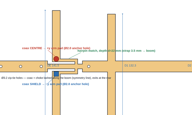
4-element cut-clad Yagi — 2 mm copper-clad FR4, zero etch
10.4 dBi D (PML_8) · 10.2 dBi realized (η 96%) · F/B 17 dB · E-HPBW 50° · S11 −17 dB @915 PML (−33 dB MUR-tuned, res 915.0) · Zdiff 39−j6 · BW(−10 dB) ~50 MHz — covers 902–928 ISM · worst 3D lobe −11.4 dBc (θ=28° elevated rear — the az cut alone overstates rear rejection by 5.5 dB) · ONE PIECE cut from 2 mm copper-clad FR4, NO etching: outline + 8 drills, no interior plunge cuts · split driven + CUT-IN HAIRPIN beta match (straps = arm support + DC ground + shunt L, d=22) · boom necked to 6 mm through the feed → coax pigtails split only ±10 mm · centre→+y arm, shield→−y arm, Ø2.0 anchor holes · 1:1 choke (4–5 beads mix 43) at the feed, coax down the boom (virtual-ground line), exits rear · 2× M4 rear mount · 334×145 mm · folded-DE variant tried & rejected: boom-through fold parks +j~100 across the feed (same as folded_yagi) · double-sided stock: same cut reads ~+14 MHz / R≈80 (S11 −12, VSWR 1.7) — print the template at 98.5% to centre it; single-sided preferred
⬗ stack-up: copper-clad FR4 2.0 mm (εr 4.3) · cut through copper+FR4, no etching · one piece + coax
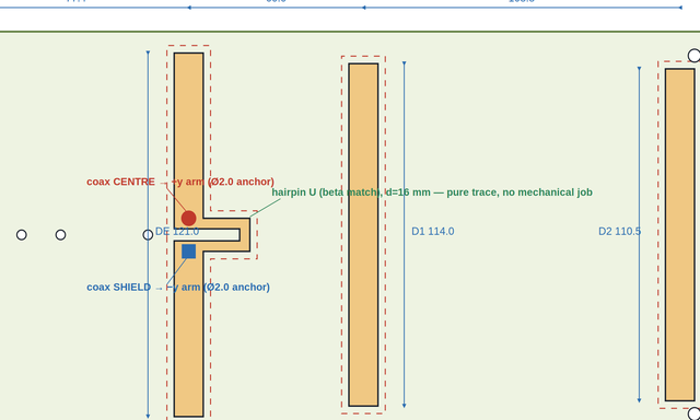
4-element boomless CNC Yagi — isolation-milled 2 mm copper-clad FR4
10.1 dBi D (PML_8) · 9.3 dBi realized (η 83%) · F/B 19.4 dB · E-HPBW 54° · S11 −17.8 dB @915 PML (−27.5 MUR-tuned, res 913.9) · Zin 48−j4 · BW(−10) 62 MHz — whole 902–928 ISM band · worst 3D lobe −13.4 dBc (down-back θ=140°) · BOOMLESS: 4 floating copper islands on an INTACT 2 mm board — CNC isolation-milled (2–3 mm moats through the foil, background peeled), board NOT cut through, nothing to snap · split DE, 4 mm gap, pigtails split only ±5 mm · textbook hairpin U trace (d=16) · centre→+y arm, shield→−y arm + 1:1 choke (4–5 beads) · coax down the centreline · optional flange-SMA through-board (pattern on schema) · 4× M4 corner mounts · 289×135 mm · full slab costs ~10% η vs outline-cut; parasitics tuned at scale 0.87 with driven −6 mm (uniform 0.84 centres match but guts F/B to 6 dB)
⬗ stack-up: copper-clad FR4 2.0 mm · board NOT cut through — copper isolation-milled, background foil peeled · 4 floating islands, no boom
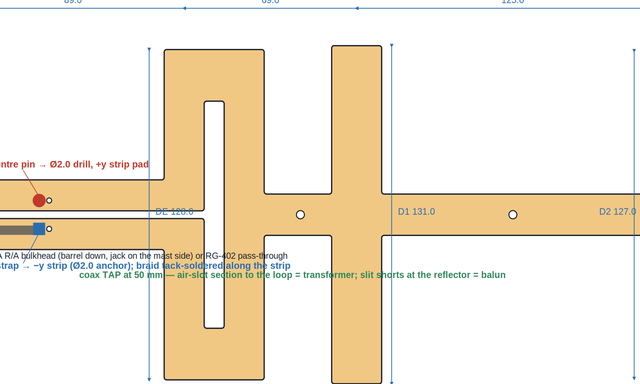
4-element loop-fed Yagi — one piece CUT from 2 mm clad FR4, SMA-jack or pigtail fed
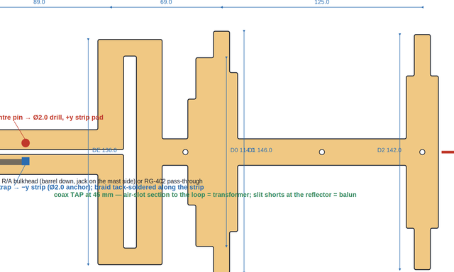
FAT element — the pair's and the rail variant's base (el 20 / rails 16 / reflector 24 / boom 16 mm: stiff, low-Q, wide): 7.7 dBi D (PML_8) · 7.5 dBi realized (η 96% — outline cut removes the dielectric loss) · F/B 25.1 dB · E-HPBW 54° · S11 −18.5 dB @915 PML (−27.6 MUR, res 915.0) · Zin 42−j8 · BW(−10) 69 MHz — 2.5× the ISM band · worst 3D lobe −4.7 dBc (down-back θ=168° — single-plane planar Yagi elevation lobes; the wide H-plane's price) · worst lobe within ±20° of the E-plane −10.8 dBc (θ=70°, φ=126°): the horizon-slab headroom, i.e. what a scanning DF receiver sees once that out-of-plane lobe is excluded · THIN corner if gain matters most (main without --fat), re-measured under identical settings: 9.11 dBi D / 9.00 realized (η 97.6%) — +1.43 dB on the FAT — and a quieter worst 3D lobe (−7.9 vs −4.7 dBc), but F/B 17.6 (−7.5), BW 51.5 (−17), res 917.3 (2.3 MHz high as drawn): the Q trade, gain vs bandwidth/F/B/tolerance · parked RG-402 A/B: ~free (res −1.1 MHz, D −0.02 dB, η −2.4 pts — the λ/4 slot balun chokes the exit path; verified with an explicit tube model, not assumed) · ONE rigid piece: reflector→slot-balun strips→folded loop→boom→directors; boom bonds the loop's continuous front rail (V-null) · slit + loop slot are through-cuts = air slotline · coax TAP 50 mm behind the loop, alt pads at 46 = high-εr rescue (slot section = transformer, slit shorts at reflector = λ/4 balun @915) · feed hardware: Amphenol Connex 132260 SMA R/A bulkhead jack in the Ø6.5 rear-tab hole — barrel down through the board (port on the mast side), nut + lock washer underneath, shell tack-soldered to the tab copper — with an ≈ 55 mm RG-400 jumper flat on the copper along y=−6 to the tap: Ø2.0 centre-pin pad (+y strip), Ø2.0 shield-strap anchor (−y strip); ALT build: bare RG-402 pigtail through the same hole · Ø3.2 M3 mounts at RF nulls (rear tab, boom nodes, boom end at the dir2 crossing — A/B'd ~free) · 323×144 mm · all drills Ø≥2 and corners r=1.0 — one Ø2 router bit does the whole part · downloads: DXF (CUT/DRILL, corners r=1) + STEP (FR4+copper solids, cadquery/OCC — imports in CST 2024) + IPC-2581C XML (geometry-level, structurally valid; not certified against the IPC schema) + 1:1 template · 3-projection 132260 connection detail + RG-402 routing drawing with tolerances + DXF render on the card · ROBUST tapered variant (own card): worst VSWR@915 1.06 over εr 4.2–4.8 where this drawing mode-crosses to VSWR 3.3+ at εr ≥ 4.4 — pick it whenever the laminate bin is unknown
⬗ stack-up: copper-clad FR4 2.0 mm · FAT elements (pair/rail base) · part CUT to the copper outline (laser or Ø2 mm route bit, corners r=1, drills Ø≥2) · FR4 only under copper · feed: Amphenol Connex 132260 SMA R/A bulkhead + RG-400 jumper (or bare RG-402 pigtail)
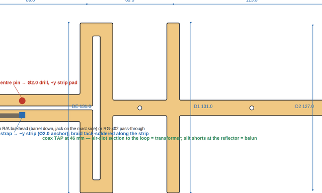
4-element loop-fed Yagi, THIN elements — the high-gain corner
THIN element (el 10 / rails 10 / reflector 14 / boom 12 mm — the original narrow cut, kept as the gain corner of the same design): 9.1 dBi D (PML_8) · 9.0 dBi realized (η 97.6%) · F/B 17.6 dB · E-HPBW 54° · worst 3D lobe −7.9 dBc (down-back θ=162°) · worst lobe within ±20° of the E-plane −13.5 dBc (θ=70°, φ=128°) — 2.7 dB more horizon-slab headroom than the FAT's −10.8, the same direction the full-sphere figure points · S11 −19.6 dB @915 PML (−28.3 MUR) · Zin 42−j5 · res 917.3 MUR (2.3 MHz high as drawn) · BW(−10) 51.5 MHz · SAME part, same envelope and spacings as the FAT headline — only the widths change, and the trade is two-sided: thin buys +1.43 dB directivity and a 3.1 dB quieter worst 3D lobe; FAT buys +7.5 dB F/B, +17 MHz bandwidth (69 vs 51.5) and lands on 915.0 exactly · that bandwidth is the tolerance margin: a mm of cut error or an FR4 εr surprise moves the low-Q FAT part WITHIN the ISM band and walks the high-Q thin one out · thin is also the floppier part (half the root section on every element) and has no alt tap pads and no rail variant — the pair, rail-mount, mount-hole/spar A/Bs and the 132260 connector detail are all measured on FAT · pick thin for a fixed, carefully built single-frequency link where 1.4 dB of range matters and elevation lobes bother you · 313×144 mm (110.9 cm² copper vs the FAT's 172.6 — but a LONGER cut path, 199 vs 193 cm, so machining time is a wash) · same Ø2-bit tooling, same Ø6.5 rear-tab bulkhead bore (Amphenol Connex 132260) and the same feed detail
⬗ stack-up: copper-clad FR4 2.0 mm · THIN elements (original narrow cut) · part CUT to the copper outline (laser or Ø2 mm route bit, corners r=1, drills Ø≥2) · FR4 only under copper · feed: Amphenol Connex 132260 SMA R/A bulkhead + RG-400 jumper (or bare RG-402 pigtail)
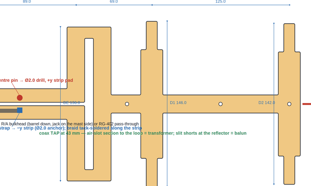
4-element loop-fed Yagi, ROBUST — tapered FAT elements, flat over the whole FR4 εr bin
The tolerance lesson from the produced board, built into copper: robustness = worst-case over what the shop cannot control — the laminate εr (stock 2 mm FR4 runs 4.4–4.7 at 915), NOT bandwidth. Envelope verdict (::envelope, MUR, εr 4.2 / 4.4 / 4.6 / 4.8): worst VSWR@915 ≤ 1.06 ACROSS THE WHOLE RANGE (1.06 / 1.03 / 1.02 / 1.02) · resonance 917.3→915.0 (2.3 MHz total drift, toward target) · BW₁₀ 79–80 MHz · D 8.85→8.92 · F/B 20.8–20.9 — every figure flat. Same boards, legacy FAT: VSWR 3.3+ at εr ≥ 4.4 (the mode crossing that killed the produced part); THIN: 1.06–1.09 (flat but flexible). MECHANISM — tip taper: 10 mm-wide tips on the outer 25 mm of every parasitic; the 20/24 mm root stays where the bending moment lives, the tips go thin where the E-field (hence the dielectric pull) lives. εr pull drops 27 → ~5 MHz per 0.3 εr and the SECOND resonance whose relative position εr steered is gone — single-tuned like THIN, stiff like FAT. Loop end-bridges thinned to 10 mm to match. ARRAY RE-TUNE — a tapered strip is a stepped-impedance resonator sitting high, and a global dim_scale cannot restore array tuning (F/B collapses to 2–3 dB, measured): each parasitic gets +15 mm additive stretch (R 159 / D1 146 / D2 142), the loop stays 136 untrimmed, tap moves 50 → 43 — ONE pad pair; the alt-pair insurance is what the taper itself now provides. Tune point (εr 4.45, MUR): res 916.1, S11 −37.7 @915, Zin 50.4−j1.3, VSWR 1.03. PML_8 @915 (εr 4.45): 8.57 dBi D · 8.47 realized (η 97.6%) · F/B 22.4 dB · E-HPBW 54° · S11 −20.5, Zin 41.5−j1.6 · worst 3D lobe −6.6 dBc (θ=168° down-back class) · worst lobe within ±20° of the E-plane −12.7 dBc — vs legacy FAT: +0.9 dB forward, lobes ~2 dB quieter, F/B −2.7 (22.4 vs 25.1). Part 323×159 mm, same one-piece rules: outline cut, Ø2 bit, corners r=1, drills Ø≥2; Ø6.5 rear-tab hole (132260 SMA R/A bulkhead or RG-402 pass-through), Ø2 centre-pin + shield-strap pads, Ø3.2 M3 mounts at the RF nulls. No rail composition yet — the hole package is unverified on tapered elements. Downloads: DXF (CUT/DRILL) + STEP (FR4+copper solids) + 1:1 template + MUR & PML result JSONs. · 40 MHz-window stability (PML_8, one run, NF2FF at 895/905/915/925/935): main lobe steady — E-HPBW 58/54/54/50/50°, forward D 7.61/8.01/8.57/9.26/9.98 dBi (the gain dome sits slightly high: director resonance above band, standard 4-el dispersion) · F/B 21.2/30.4/22.4/16.0/12.1 dB — the in-window WORST (12.1, at 935) still beats the gerber quasi-Yagi card's 915 headline (9.1) · impedance at the PML plane: R 60→31 Ω, X −18…+23 Ω across the window, VSWR ≤ ~1.55 inside the ISM band and 2.08 only at the 935 extreme (MUR tap-plane curves: ≤ 1.1 across the whole window at every eps — the MUR→PML S11 shift is the same class seen on the legacy FAT/THIN finals) · STABLE sibling (own card): + one OWA matching director → F/B spread 3.3 dB and VSWR ≤ 1.45 across the ISM band with the eps-immunity kept — pick it for frequency-hopping DF; this card stays the max-F/B corner
⬗ stack-up: copper-clad FR4 2.0 mm · FAT roots (el 20 / refl 24) tapered to 10 mm tips over the outer 25 mm · +15 mm parasitic stretch, tap 43 single pair · part CUT to the copper outline (laser or Ø2 mm route bit, corners r=1) · FR4 only under copper · feed: Amphenol Connex 132260 SMA R/A bulkhead + RG-400 jumper (or bare RG-402 pigtail)
4-element loop-fed Yagi, STABLE — OWA-matched, flat impedance AND pattern across the band, on any FR4
Both stabilities in one part — vs FREQUENCY (a hopping DF receiver sees the same antenna at every channel) and vs the LAMINATE (any stock FR4 bin). Geometry = the ROBUST tapered-FAT plus one extra strip: an OWA matching director (Breakall) — root 20 mm tapered to 10 mm tips like every parasitic, L 114, its leading edge 16 mm off the loop's front rail, boom-carried and bonded at its voltage null; tap re-tunes 43 → 45. WHY IT WORKS — impedance: with Q ≈ 11 a single-tuned match CANNOT hold VSWR ≤ 1.3 over 40 MHz (Fano bound); the close-coupled D0 adds the second pole (the classic OWA direct-50 Ω mechanism) and the Zin locus stops transiting 50 Ω and CURLS around it — and because the D0 is tip-tapered, the second pole rides the laminate exactly like the first. Pattern: the D0 re-shapes the array response so the F/B dome sits on the band instead of a point. MEASURED, PML_8 @ eps 4.45, one run, NF2FF at 895/905/915/925/935: F/B 17.3 / 20.6 / 21.8 / 18.5 / 14.7 dB — ISM-band spread 3.3 dB (ROBUST: 14.4, legacy FAT worse) · worst in-window F/B 14.7 still above the gerber quasi-Yagi's 915 headline (9.1) · D 7.49 dBi at 915, in-band spread 0.8 dB (η 97.2%; the ~1.1 dB vs ROBUST is the flatness price) · E-HPBW 58/58/54/54/50° · VSWR at the PML plane 1.55/1.40/1.34/1.43/1.69, ≤ 1.45 inside the ISM band (ROBUST hit 2.08 at the 935 corner). LAMINATE ENVELOPE (MUR, eps 4.2/4.4/4.6/4.8): VSWR@915 = 1.22/1.18/1.18/1.18 — worst 1.22 · res drift 3.4 MHz · BW₁₀ 90–92 MHz (the double-tuning dividend; ROBUST 79) · D and F/B constant to 0.04/0.1 dB · even the band-edge F/B triplet is eps-invariant (spread ≤ 0.5 dB): the frequency-stability is itself laminate-proof. Tuning history on the card charts: director stretch measured WRONG (top-edge F/B worsens), wide/untapered reflector measured WRONG (match degrades at 40 mm width, breaks at 60) — the OWA director is what works. Part 323×159 mm, one piece, same cut rules (Ø2 bit, r=1, drills Ø≥2), Ø6.5 rear-tab hole for the 132260 SMA bulkhead, single tap pair at 45. No rail/pair composition yet — unverified with the D0. Downloads: DXF + STEP + 1:1 + MUR & PML result JSONs.
⬗ stack-up: copper-clad FR4 2.0 mm · ROBUST tapered-FAT base + OWA matching director (D0 114, gap 16, boom-carried) · tap 45 single pair · part CUT to the copper outline (laser or Ø2 mm route bit, corners r=1) · FR4 only under copper · feed: Amphenol Connex 132260 SMA R/A bulkhead + RG-400 jumper (or bare RG-402 pigtail)
Moxon 4-el quasi-Yagi — a915 respin, same rear-tab SMA
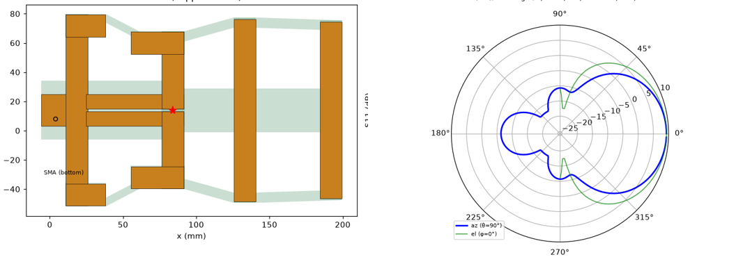
9.30 dBi · F/B 15.6 dB · F/WORST-3D-LOBE 14.2 dB @915 (max lobe anywhere behind the x=0 plane, full-sphere scan — the DF ambiguity headroom) (14.1/15.6/16.4 across 895/915/935 — the F/B skirt rises with falling res; the deep null sits ~50 MHz above resonance so 915 rides its skirt) · KEY DF FINDING: the horizon-plane (az) rear null and the 3D-worst-lobe are ANTI-CORRELATED — closing the Moxon gap C deepens the az null (F/B@915 14.5→15.6→16.8→17.8 as C 18.5→17.5→16.5→15.5) but pumps a +70°-ELEVATION rear lobe, so F/worst-3D-lobe FALLS 14.5→14.2→13.6→13.2; loose C is best for full-3D DF rejection, tight C for a near-horizon 2D F/B spec. SHIP (C 17.5) recovers the 3 mm-apron rev-B az-F/B while keeping the 3D lobe at the horizon · S11 -19.7 dB @915 (Zin 61+4j — direct 50Ω, no matching network) · vs the AS-ORDERED a915_4el_final it is based on (same rig, PML_8 port-at-neck: 9.08 dBi · F/B 10.4 (10.1/10.4/11.4) · F/worst-3D 10.4 · S11 -32.5): +0.22 dB gain, +5.2 dB F/B, board 179.4→131.5 mm tall (-27% area) · MOXON bend on the ordered board: reflector 130.5 straight + 15 mm tips folded FORWARD 12, driven 107 tip-to-tip + tips folded BACK 21, coupling gap C 17.5 mm kept FR4-free (the gap rail is ONE 6 mm diagonal band, reflector apron -> driven apron, no pocket; CONSISTENT 0.5 mm JLC-min apron around reflector AND driven (routed-outline copper-to-edge 0.3 min, ±0.2 tol → 0.5 recommended), boom kept; r1 fillets = router min) · directors, spacings, GCPW feed, 58 mm reflector-shorted slotline balun and the BACK-MOUNTED CONNECTOR unchanged from the ordered board: 4-leg flange SMA THT on the BOTTOM of the rear tail tab, pin (3.97, 8.0) drill 1.2, legs 1.4 on a 5.0 mm square, M3 mounts (0,0)/(0,28) — coax centre = SMA pin → GCPW → neck → +y arm; shield = flange legs → stitched tail pour → reflector · solder points + balun drawn in the feed schema; fab zip parses clean (gerbonara) · Gerber + STEP + DXF (CST Studio 2024-ready: import the STEP as solids — FR4 + both copper layers, drills cut — or the layered DXF — BOARD/COPPER_TOP/COPPER_BOT/DRILL/PORT — and extrude; CST_README in the zip has the steps + the 50Ω discrete-port placement across the slot at the neck) · ALTERNATE dims on the same board (one-knob swaps, PML-verified): match-optimal l_drv 109 / l_refl 128 / tip_back 19 → S11 −32.3 dB (VSWR 1.05), 9.41 dBi, F/B 12.2 (F/worst-3D 12.3); max-horizon-F/B tip_back 22 (C 16.5) → az-F/B 16.8, F/worst-3D 13.6, S11 -16.7 (near-horizon emitters) · every PML final stores its FULL-SPHERE 3D result (D(θ,φ) + S11/Zin curves + params) on the antenna-sim-cache Modal volume for reuse — monopulse pairing / DF templates / re-scored metrics without re-solving (a915_moxon.py::cache_ls, ::cache_get) · MUR ladders s1–s4 (35 s/run, 2-CPU containers) + PML_8 finals; az-cut worst-rear ±60° 15.6 dB
⬗ stack-up: FR4 1.6 mm (εr 4.3) · 1 oz Cu · 2-layer, via-stitched (Ø0.5) · rounded r2 outline, hugged ribs + diagonal gap rail, moxon gap FR4-free · rear-tab SMA (bottom face)
Feed network & array
Rat-race coupler (180° hybrid)
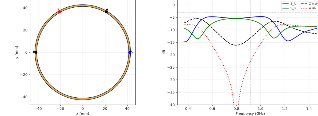
Σ/Δ monopulse feed · isolation −23 dB · Σ 0°, Δ 180°
⬗ stack-up: FR4 1.6 mm (εr 4.3) · 1 oz Cu (35 µm) · microstrip + bottom ground
Monopulse 2-Yagi array
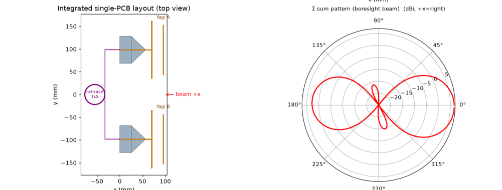
Σ beam 6.6 dBi · Δ boresight null · quasi-Yagi + rat-race
⬗ stack-up: FR4 1.6 mm (εr 4.3) · 1 oz Cu (35 µm) · 2-layer (top + ground)
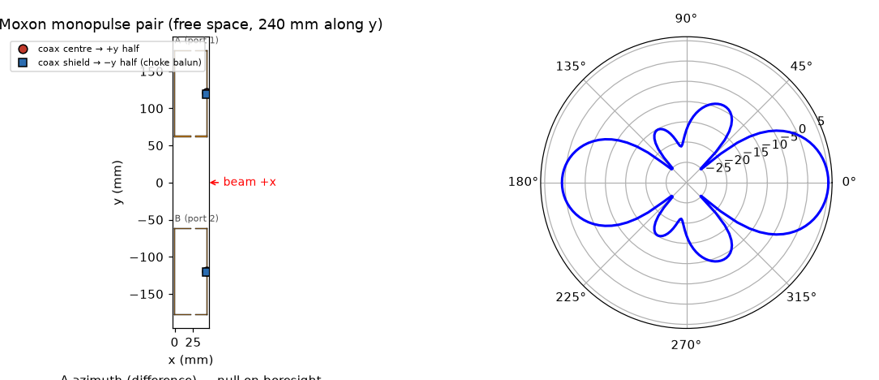
Moxon monopulse pair (free space)
Σ 5.1 dBi · Σ F/B only 4.4 dB — the single Moxon's 30 dB null collapses under array mutual coupling (PML-confirmed) · Δ null −30 dB · +3.0 dB array · ±32° Δ lobes · 240 mm (0.73λ) · ideal coupler
⬗ stack-up: free-space sheet metal/wire (no substrate)
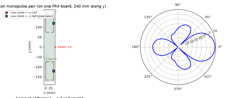
Moxon monopulse pair on FR4
Σ 9.0 dBi D (~8.2 realized) · Σ F/B 12.2 dB · Δ null −38 dB · +3.0 dB array · ±32° Δ lobes · 240 mm (0.73λ) · one FR4 board · ideal coupler
⬗ stack-up: FR4 1.6 mm (εr 4.3) · 1 oz Cu (35 µm) · single top layer
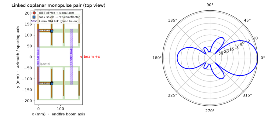
Coplanar monopulse pair + 2 FR4 links (glued under)
Σ 11.0 dBi (+2.9 dB array) · Σ F/B 12.7 dB (= element F/B — the sum adds gain, not F/B; the pair beats the single element's 9.3 dB via reflector mutual coupling, NOT the sum) · Δ null −35 dB · ±28° Δ lobes · res 915 MHz (S11 −33 dB) · 240 mm (0.73λ) · TWO IDENTICAL 4 mm FR4 links (12×252 mm) glued to the board UNDERSIDE (rear across the reflectors + front across the boom spines) — FDTD(PML_8)-verified benign: Δf_res 0 MHz, ΔΣ-peak −0.06 dB, ΔΔ-null −0.2 dB · l_drv 130.5 (PML-tuned: the pair resonates ~22 MHz below the single because the two large reflectors couple) · links land on the reflector/boom-spine voltage nulls, clear of element tips & the feed slot · 1 layer slotline balun · ideal coupler · PML_8 (accurate gain)
⬗ stack-up: FR4 1.6 mm (εr 4.3) · 1 oz Cu (35 µm) · single top layer, ribbed · 2× 4 mm FR4 ties (12×252 mm) glued underneath
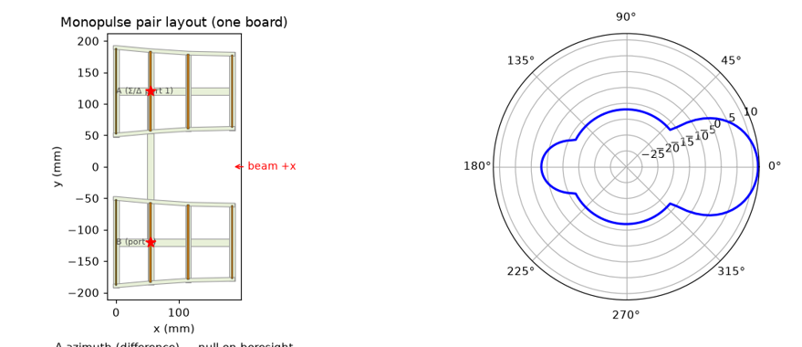
Monopulse pair — 2× ribbed PCB Yagi
Σ 11.6 dBi (+2.8 dB array) · Σ F/B 14.8 dB · Δ null −23 dB · ±26° Δ lobes · 240 mm (0.73λ) · ideal coupler
⬗ stack-up: FR4 1.6 mm (εr 4.3) · 1 oz Cu (35 µm) · ribbed frame
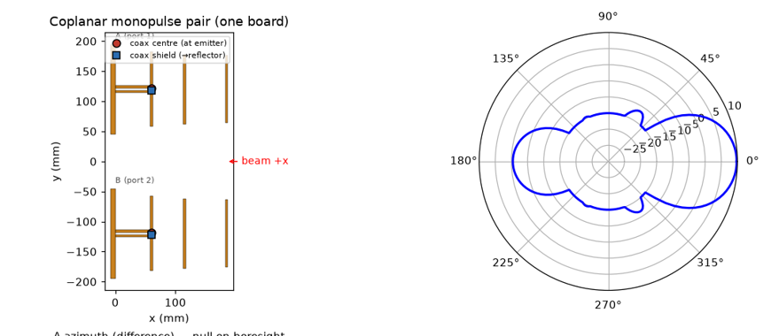
Coplanar monopulse pair (2× 1-layer quasi-Yagi)
Σ 9.8 dBi (+2.95 dB array) · Σ F/B 10.2 dB · Δ null −25 dB · ±28° Δ lobes · 240 mm (0.73λ) · ideal coupler · 1 layer · slotline balun
⬗ stack-up: FR4 1.6 mm (εr 4.3) · 1 oz Cu (35 µm) · single top layer
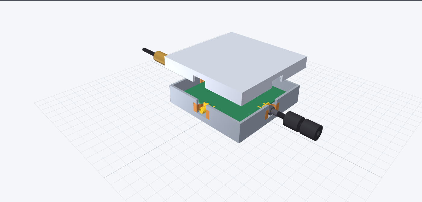
Wideband rat-race — 180° phase inverter + shielded box
915 MHz · Δ-phase flat 180° over ~124 % band, Σ↔Δ iso >20 dB over ~92 % (inverter = CPS strip-swap crossover; conventional ring ~25 %) · split −2.6/−3.8 dB · 3D-printed Cu-tape box, cavity mode ≈2.2 GHz · interactive 3D on the detail page (mated cable + solder collars)
⬗ stack-up: FR4 1.6 mm CPS (no ground plane) · 3D print + Cu-tape wrap · WE 60312202114509 SMA ×4
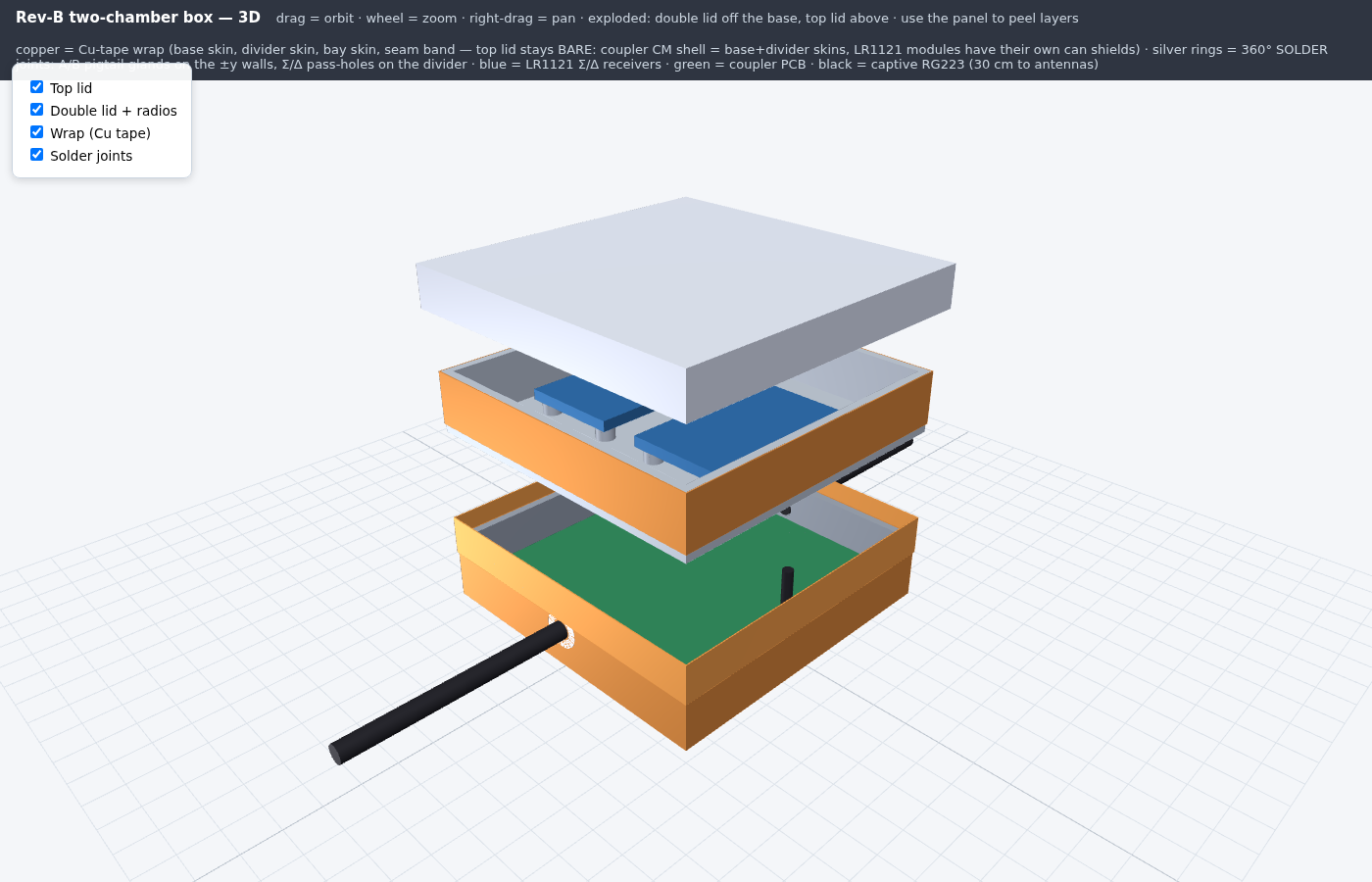
Rev-B two-chamber box — coupler below, two LR1121s inside the double lid
915 MHz · 95×95×41.5 mm 3-part print (base / double lid / top), all parts print flat, no supports · coupler cavity 90×90×18 (first cavity mode ≈2.36 GHz — clear of 915 and its 2nd harmonic), radio bay 16 mm above the divider with two LR1121 modules on bosses · NO connectors through the shield: captive double-shielded pigtails (30 cm RG223 to the antennas) pass through fully-closed Ø6.2 glands, outer braid soldered 360° into the Cu-tape wrap — the gland360 scheme measured −57 dB common-mode in FDTD (vs straps −40, straps+λ/4 sleeve −59, unbonded/no box −21) · Σ/Δ to the radios cross the divider as double-shield micro-coax through pass-holes with 360° solder rings · Cu-tape wrap: base skin + divider skin + bay walls, base↔bay seam closed by a vertical tape band — the TOP LID stays bare plastic (the coupler's CM shell is base+divider skins and the LR1121 modules carry their own can shields, so a taped top adds nothing) · interactive 3D below: two-stage explode (double lid off the base, top lid above) with hideable layers: top lid / double lid + radios / Cu-tape wrap / solder joints
⬗ stack-up: 3D print, 3 flat parts 95×95×41.5 mm · Cu-tape wrap + seam band · captive RG223 ×2 (antennas) + double-shield micro-coax Σ/Δ · 2× LR1121 in the lid bay
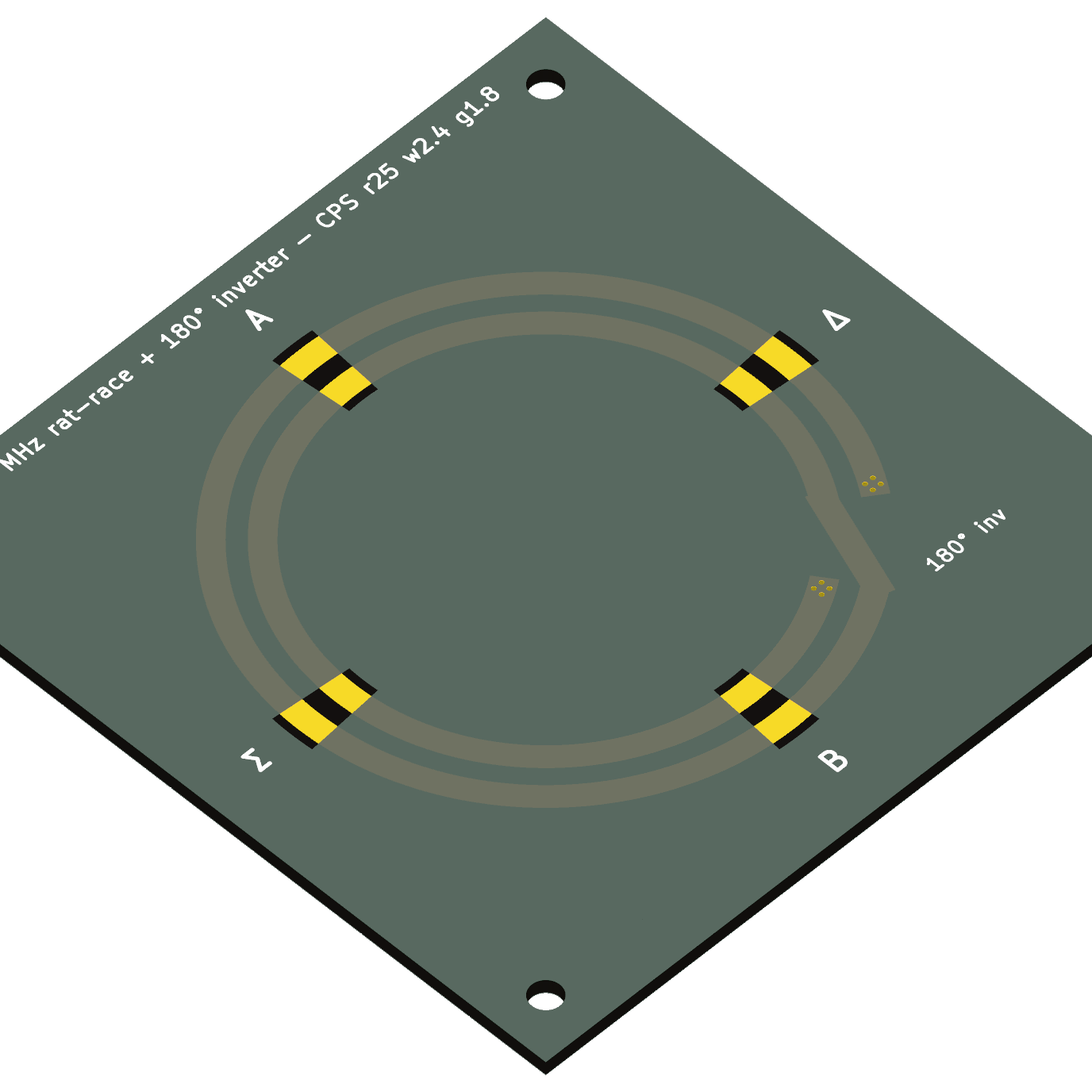
Rat-race coupler board — KiCad, DRC-clean, interactive
915 MHz CPS ring (r25 · w2.4 · gap1.8) authored as a .kicad_pcb from the SAME param dict as the FDTD model — no GUI in the loop · KiCad 9 headless on Modal: DRC 0 violations / 0 unconnected, Gerbers+drill fab-ready, board STEP, raytraced renders · copper: two ring annuli broken over the 315°±10° window, top diagonal + bottom underpass + 2×2 via farms = the 180° inverter · solder-mask windows at the Δ/A/Σ/B ports (pigtails solder straight across the CPS gap) · 78×78 board, M3 mounts matching the rev-B box bosses — fit-checked in cadquery against the box CAD: 6.0 mm wall gap, 0 mm³ interference, pilots clear · fully interactive board below (KiCanvas: pan/zoom, layer toggles, object inspect)
⬗ stack-up: FR4 1.6 mm · 1 oz Cu · 2 layers · 78×78 mm · authored + verified headless (kicad-cli on Modal)
Direction finding (monopulse DF)
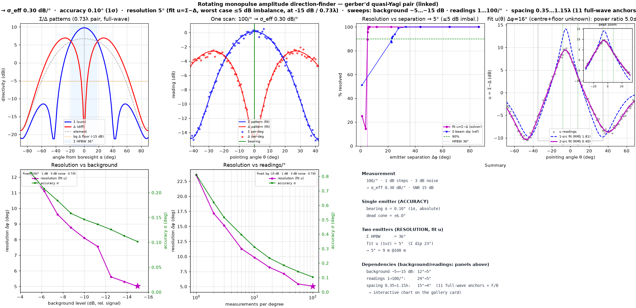
Monopulse amplitude DF — gerber'd quasi-Yagi pair (linked)
ROTATING monopulse (log Σ/Δ amplitudes, no phase) → absolute bearing, no sign ambiguity · full-wave Σ/Δ pair of the ACTUAL gerber'd element (gerber_yagi, digitised from the uploaded Gerber set; single-element re-check 8.9 dBi / 902 MHz / S11 −24 dB @915), mechanically joined by TWO identical 12 mm-wide × 2 mm FR4 backing splice strips placed ONLY on the voltage-null lines (matching the coplanar_monopulse_linked convention): REAR across the reflectors and FRONT across the boom spine BETWEEN dir-1 and dir-2 — longitudinal field minima, off every element tip and the feed slot. Each tie is now LENGTHENED in y to fully CROSS each board's ~22 mm copper boom (overrunning it by 4 mm), so the two boards can be screwed + bonded into one rigid pair with real overlap — re-simulated at the 0.60λ design point this is RF-negligible (ΔΣ F/B 0.03 dB, Δ null 0.06 dB, gain unchanged), since the ties still ride the longitudinal field-null spine; they still deepen the Δ null to ≈−28…−34 dB (vs −21…−25 dB unlinked) · measurement: 100 readings/°, 1 dB detector steps, 3 dB noise (dither) → σ_eff 0.30 dB per 1° reading · single-emitter ACCURACY 0.10° (1σ) · two-emitter RESOLUTION 5.0° for UNEQUAL emitters (WORST case, powers within 5 dB), by a 1-SOURCE GOODNESS-OF-FIT of u=Σ−Δ with the single-source null free in bearing (CFAR 5%) — ~7× below the 36° Σ beamwidth (≈8.8 m @ 100 m) · resolution depends on: background −5→−15 dB ≈ 12°→5° · readings 1→100/° ≈ 24°→5° (accuracy 0.8°→0.1°) · pair spacing 0.35→1.15λ ≈ 15°→4.5° — shape-preserving interpolation THROUGH 11 full-wave anchors (0.40λ 14.9° · 0.50λ 5.3° · 0.52λ 5.4° · 0.54λ 5.2° · 0.56λ 5.1° · 0.58λ 5.2° · 0.60λ 5.2° · 0.73λ 5.0° · 0.85λ 4.7° · 1.0λ 4.6° · 1.15λ 4.5°) · REFINED 0.50–0.60λ band for max Σ front/back: F/B rises 7.5→8.6 dB across the band and PEAKS at 8.6 dB @ 0.60λ (196.7 mm) — the best-F/B spacing between the reflector-merge floor below ≈0.50λ and the nominal 0.73λ (F/B then falls to 8.0 dB by 0.73λ) · 0.40λ is far coarsest (the 179 mm reflectors merge → near-bidirectional, Σ F/B −0.8 dB), >1λ shaded (grating lobes → ambiguous bearing) · the SAME u=Σ−Δ scan reads out an UNEQUAL pair's power ratio via a continuous 2-source fit with pair CENTRE free + noise floor from the ROTATION MINIMUM (neither assumed known): at a resolved 16° split, ratio 5.0±0.3 dB, centre ±0.3°, floor ±0.1 dB
⬗ stack-up: FR4 1.6 mm (εr 4.3) · 1 oz Cu (35 µm) · single layer, routed flared frame 215.5×179.3 mm per element · 2× 2 mm FR4 back-tie splice strips (reflector + dir1/dir2 field nulls) · 2-element Σ/Δ @ 240 mm (0.73λ); best F/B @ 0.60λ
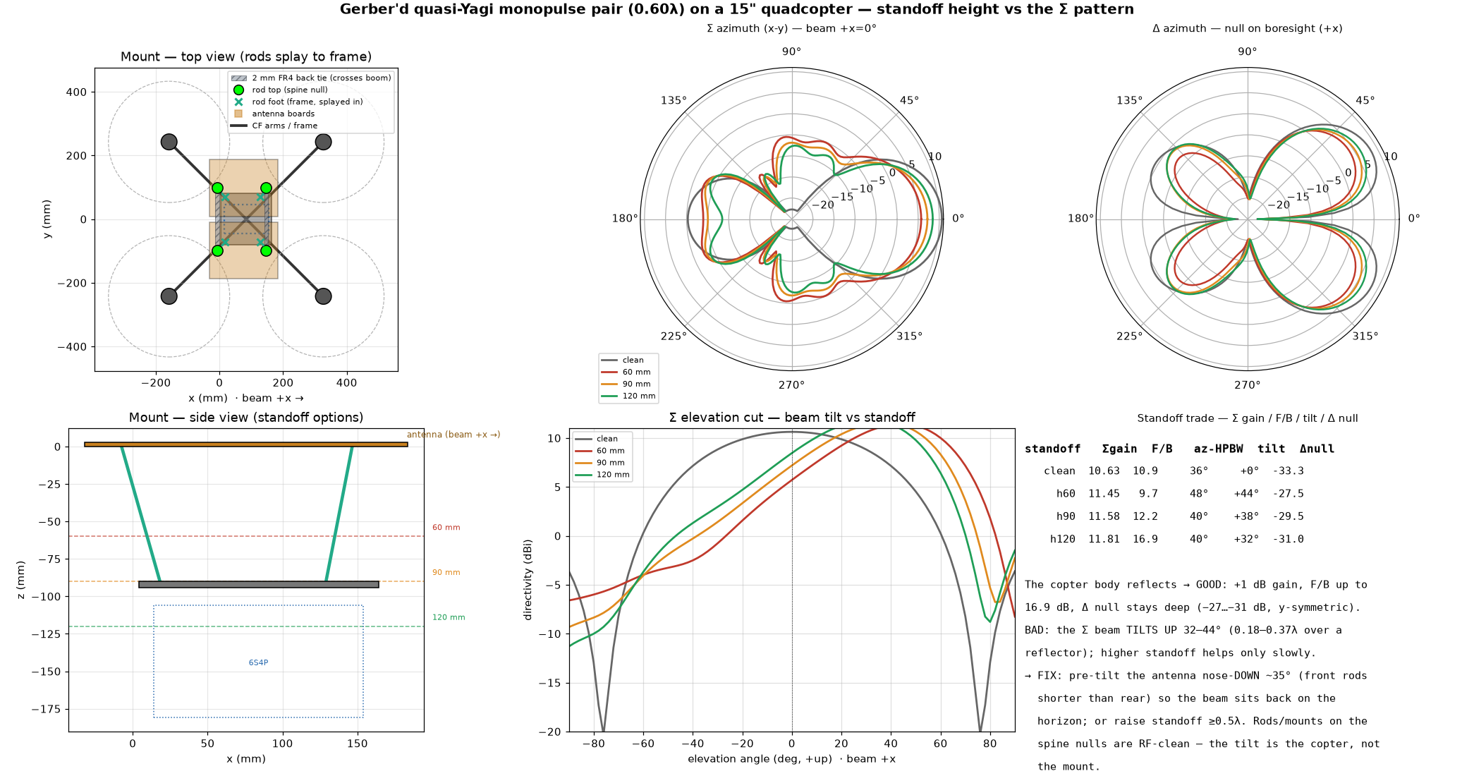
Monopulse DF pair on a 15" quadcopter — mount, standoff, mechanics, flight
The 0.60λ (max-F/B) gerber'd quasi-Yagi Σ/Δ pair mounted FLAT ON TOP of a 15" quad (686 mm wheelbase, CF plate + 4 arms + 4 motors, 6S4P 21700 pack under) on 4× Ø5 mm GLASS-FIBRE rods that SPLAY inward (inclined quadpod) from the two boards' boom-spine VOLTAGE-NULL lines (rear reflector station x=−7.5, front dir1/dir2 gap x=146.5, y=±98.4) down to the CF plate — a wide 154×197 mm top footprint, RF-clean, each rod capped in a 3D-printed bracket screwed to the spine and glued to the rod; the two boards are spliced by TWO 12 mm × 2 mm FR4 back-ties on those same spine null lines, LENGTHENED to CROSS each board's boom so the pair is one rigid connected unit (RF-negligible, ΔΣ F/B 0.03 dB) · interactive 3D model embedded below (shows the boom-crossing ties + rod brackets) · RF (full-wave PML, standoff 60/90/120 mm vs clean): the copter body acts as an extra reflector → GOOD Σ gain +0.8…1.2 dB (→11.4–11.8 dBi), Σ F/B up to 12–17 dB, Δ null stays deep (−27…−31 dB, copter symmetric about the array axis) — BUT the Σ beam TILTS UP 44°→38°→32° over 60→120 mm (horizontal antenna 0.18–0.37λ over a reflector); FIX = nose-DOWN ~35° pre-tilt (front rods shorter) or standoff ≥0.5λ (see the ELEVATION-PLANE diagram: clean peaks on the horizon, the mounted lobe lifts to +32…+44°, and a nose-down pre-tilt rotates it back); the splayed thin rods on the null lines are RF-negligible (pattern unchanged vs no rods) · MECHANICAL (analytic, 151 g assembly): the SPLAY carries LATERAL/tilt loads AXIALLY → lateral fn ≈ 855 Hz, and even a drone bank only puts m·g·sinθ through the rods as axial (SF ≈ 2250 @6 g, buckling ~6 kN/rod). BUT a lateral-only view is incomplete: the DF-critical axis is YAW (a Δ-null twist vs the drone is a 1:1 bearing error, spec < 0.1° = 100 m°). Yaw is bending-resisted (~7× softer, ~125 Hz rigid-ideal, in the 2P band) AND — decisively — the 4 near-radial rods react ~94% out-of-plane onto the 1.6 mm board, which is ~1300× too soft there, so yaw is effectively an UNCONSTRAINED MECHANISM through the floppy PCB (skewing the feet only couples g→yaw and still pushes out-of-plane). FIX = an 8-strut DIAGONALLY-BRACED quadpod (4 rods + 4 wall diagonals, shown in the 3D with a 6/8-strut toggle): the diagonals react every node AXIALLY → stiff in all 6 DOF (lowest mode ~370 Hz, above the 2P band), so the Δ-null stays within 0.1° vs the drone under gust + brisk yaw; 8 struts are REDUNDANT/fail-safe; the BEST minimal 6 (toggle in the 3D) is an OCTAHEDRAL hexapod on a 3-POINT KINEMATIC attach along the null ties — 1 on the reflector-tie mid-span (between the boards, RF-quietest; that tie is board-backed so its free span is ~17 mm) + 2 on the dir1/dir2 tie at the boom bonds (elsewhere it spans routed windows) — base triangle anti-aligned on the plate: a yaw torque puts ZERO out-of-plane force on the board (carried in-plane, the ~90× stiffer direction), 3-point support cannot warp the boards, zero g→yaw coupling. CAVEAT the 3-pt attach leaves the reflector rear corners ~200 mm from any support → 0.66 mm/g droop flapping at 24 Hz, so the design INCLUDES a 15×5 G10 REAR SPAR (full width) + 12×6 ribs (+110 g) with RF-DRIVEN placement — FDTD @0.60λ measured a spar ALONG the reflector line costs 0.40 dB Σ F/B (near-field loading), so the spar sits at the board REAR EDGE behind the reflector copper and the ribs at the OUTER spine edge ~10 mm off the feed slot (measured cost: ΔF/B 0.05 dB, gain −0.04 dB, Δ null unchanged — negligible): coupled flexible-board model then gives board modes ≥44 Hz, sag 0.04 mm/g, yaw 715 Hz — beating the 8-strut on every stiffness number, but statically determinate = collapse on one strut/bond loss (fail-safety is the 8-strut's case). Splitting the rear attach into two (4-pt/6-strut) fixes the droop without a spar but leaks in-plane loads out-of-plane at the un-paired points (~23 Hz coupled sway); V-pairs at all four points = the 8-strut. A valid 6 must also be non-singular — 4 parallel radial rods are rank-3, not 6. Separately, the 1.6 mm FR4 element overhangs flap out-of-plane at ~106 Hz (in-band) → add a STIFFENING RIB along the elements; that flap is elevation-only (2nd-order for azimuth bearing). Prior "over-built, keep stiff, no resonance" verdict SUPERSEDED by this braced/ribbed design · PROP-FLOW loads are small (steady 73 mN, unsteady 2P 143 mN, 1P imbalance 142 mN/motor) and with fn≫excitation see ≈1× amplification → ~0.1 µm sway, no fatigue/microphonics · FLIGHT (3.5 kg AUW, 6S4P ≈346 Wh usable, FM 0.60): endurance HOVER ~45 min, MAX ~57 min @ 10 m/s (translational lift beats hover), ~33 min @ 20 m/s; MAX RANGE ~45 km @ 16 m/s; the antenna costs ~3 min at hover (mass), ~4 min/4 km at loiter/cruise, ~6 min by 20 m/s (board pitches to 22° → 3.1 N drag, +19% cruise power) · SIDE-GUST DF MOVEMENT (hover): the stiff splay tilts the array only ~0.06 m° in a 15 m/s gust +2 g correction (≪ the 100 m° DF accuracy) → the array is effectively RIGID to the drone/IMU frame, gusts don't corrupt the bearing · VERDICT: structurally + for DF-pointing stability ROBUST (over-built, off-resonance, gust-immune); the one gating item is the RF beam uptilt — commit to the nose-down pre-tilt / higher standoff and validate it, then green end-to-end · plastic props + printed brackets RF-transparent, not modelled; numbers are analytic + indicative (the mounted RF runs decayed to −23…−27 dB)
⬗ stack-up: 0.60λ Σ/Δ pair (2× routed FR4 + 2 mm FR4 back-ties) · 4× Ø5 mm glass-fibre rods SPLAYED (inclined quadpod) to a 15" CF quad · 3D-printed spine brackets · 6S4P 21700, ~3.5 kg AUW
Moxon Σ/Δ pair on a 1.6 m fixed-wing — one routed strip, beam along the wing
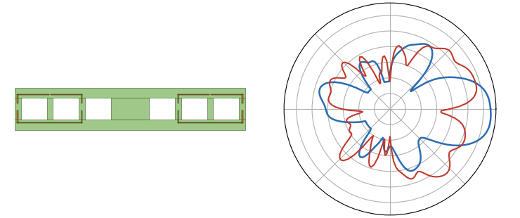
SIDE-LOOKING monopulse for a fixed-wing (Ranger-1600 class): ONE routed FR4 strip (61×342 mm, 41 g vs 62 g solid) flat on the wing-top/deck on 4× M3 nylon posts (25 mm, nyloc) — two FR4 Moxon rectangles at 240 mm (0.73λ) along the FLIGHT AXIS, beam +x ALONG THE WING, Δ-null plane abeam: orbit/flypast DF; the rotating-monopulse finder chain applies with the heading sweep · BUILD SPEC (PML, moxon-family mesh): dim_scale 0.815 / gap C 10.2 mm (element 95.5×41.1 mm) → res 915.0 MHz, S11 −20.5 dB, Zin 46.8+8.6j — direct 50 Ω, no matching network · CLEAN PAIR: Σ 8.9 dBi · Σ F/B 13.8 dB · HPBW 36° · Δ null −34.9 dB · η 91.2% · OPTIMAL CUTOUTS, FDTD-settled: FR4 kept only at two full-length rails + 4 mm trace aprons + per-element coax SPINES (element-centreline transverse-E nulls) + centre web — 6 windows routed out, −35% mass; the windows UNLOAD the arms, so the published solid-board gap (8.8 mm) under-couples — re-balancing C 8.8→10.2 mm recovers the Moxon null; after re-balance the routed board BEATS solid on the same-mesh A/B: Σ −0.2 dB · F/B +3.1 dB · η +5.9 pts · Δ null equal · 41 vs 62 g · MOUNTED (full-wave PML with the airframe conductors: Ø8 CF spar ALONG the beam 40 mm under the board — crosses the elements at 90°, 2× CF tail rods PARALLEL under the aft element, LiPo, pusher motor, harness; runs converged to −40 dB): Σ 7.3 dBi at the horizon (beam tilts +30° up, peak 8.1 dBi — the broad Moxon H-plane makes the tilt cost only ~1.3 dB; banking toward the target in an orbit rolls it back), Σ F/B 11.6 dB, Δ null −16 dB @ −2° (the battery-vs-motor fore/aft asymmetry shifts the null 2° nose-ward — a DF calibration constant, like the measured template's −2.6° squint; −16 dB ≈ the −15 dB operational background floor that the interference study showed is the real limit), S11@915 −21.5 dB — mounting detunes +18–22 MHz, the 25 mm standoff is the trim knob · FINDER ON THE MOUNTED PATTERNS (100 rdg/°, 1 dB steps, 3 dB noise, bg −15 dB): bearing accuracy 0.13° (1σ) · two-emitter resolution 5.0° · Σ HPBW 32° — airframe scatter costs ~nothing vs the clean cards (0.10°/5.3°) · MOUNT: posts on the rails at the element centrelines (E-nulls); plate modes ≥~330 Hz, nylon sway <65 Hz → the 133–200 Hz prop band stays clear; coax UNDER the board on the spines, EQUAL length, 5-bead ferrite choke at each feed (centre→aft arm pad, shield→fwd arm pad), rat-race Σ/Δ hybrid below deck (see the rat-race card) · FLIGHT COST (biquad_flight model): ~0.10 N @ 12 m/s + ~100 g installed → 77→66 min endurance (−14%; the biquad plate build costs −26% on the same model) · mesh protocol: build spec + clean absolutes on the eps-scaled moxon-family mesh; cutout A/B + mounted deltas on a snapped air-bulk λ/20 twin (clean-centred at 0.83/12.5), each vs its own same-mesh baseline — cross-policy scatter ±10 MHz / ±2 dB F/B; near-coincident mesh lines snapped <0.35 mm (the unsnapped PML airframe runs went late-time unstable) · cutting DXF
⬗ stack-up: FR4 1.6 mm (εr 4.3) · 1 oz Cu (35 µm) · single top layer, ONE routed strip 61×342 mm (41 g, 6 windows) · 2× Moxon Σ/Δ @ 240 mm (0.73λ) along the flight axis · 4× M3 nylon posts 25 mm · Ranger-1600-class conductor set
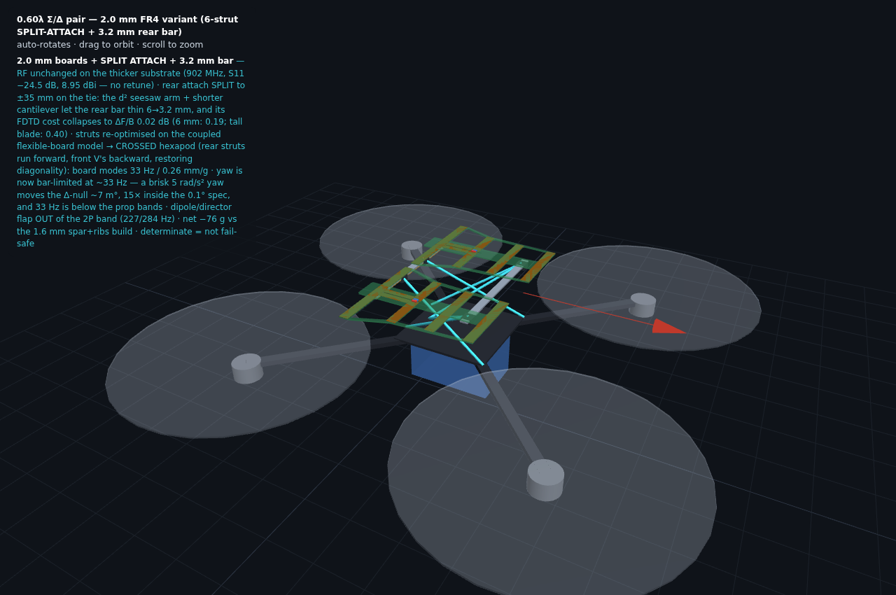
Monopulse DF drone mount — 2.0 mm variant (split-attach crossed hexapod + 3.2 mm rear bar)
VARIANT of the drone-mounted 0.60λ Σ/Δ pair: boards on 2.0 mm FR4 and the REAR ATTACH SPLIT to ±35 mm on the reflector tie — the split gives the seesaw mode a d² restoring arm and shortens the bar's cantilever, so the rear tie only needs 2→3.2 mm G10 (vs 6 mm at a single centre point), and the FDTD cost of dielectric on the reflector line COLLAPSES: ΔΣ F/B 0.02 dB (8.58→8.56; 6 mm bar: 0.19; 15-tall blade: 0.40) — gain and Δ-null unchanged · RF also unchanged by the 2.0 mm substrate itself (single-element FDTD: 902 MHz, S11 −24.5 dB @915, 8.95 dBi → NO element retune) · MOUNT: 6-strut CROSSED hexapod, feet re-optimised on the coupled flexible-board model (rear struts from the ±35 split points run FORWARD to (164,±80); front V's from the boom bonds run BACKWARD to (4,±42)+(24,0) — the crossing restores the diagonality the split destroys) · COUPLED model: first board mode 33 Hz (same as the 6 mm single-point design; 8-strut = 32), reflector sag 0.26 mm/g (0.24% λ at 3 g — RF-invisible) · TRADEOFF stated: splitting re-introduces the yaw z-leak (±z at the two points → bar seesaw in series), so yaw drops from 715 Hz (single-point octahedral) to a bar-limited ~33 Hz — a brisk 5 rad/s² drone yaw moves the Δ-null ~7 m°, still 15× inside the 0.1° DF spec, and 33 Hz sits below the prop bands (no resonance) · dipole/director overhang flap OUT of the 2P band (227/284 Hz) · LEDGER vs the 1.6 mm spar+ribs build: boards +24 g, bar +10 g, spar+ribs −110 g → NET −76 g and two fewer bonded parts · CAVEAT statically determinate (collapse on one strut/bond loss) — for fail-safety use the 8-strut braced mount on the main drone card · interactive 3D below
⬗ stack-up: 0.60λ Σ/Δ pair (2× routed 2.0 mm FR4) · rear tie 12×3.2 G10 (split attach ±35 mm) + front tie 12×2 · crossed 6-strut GFRP hexapod, coupled-model-optimised feet · 15" quad, CF frame
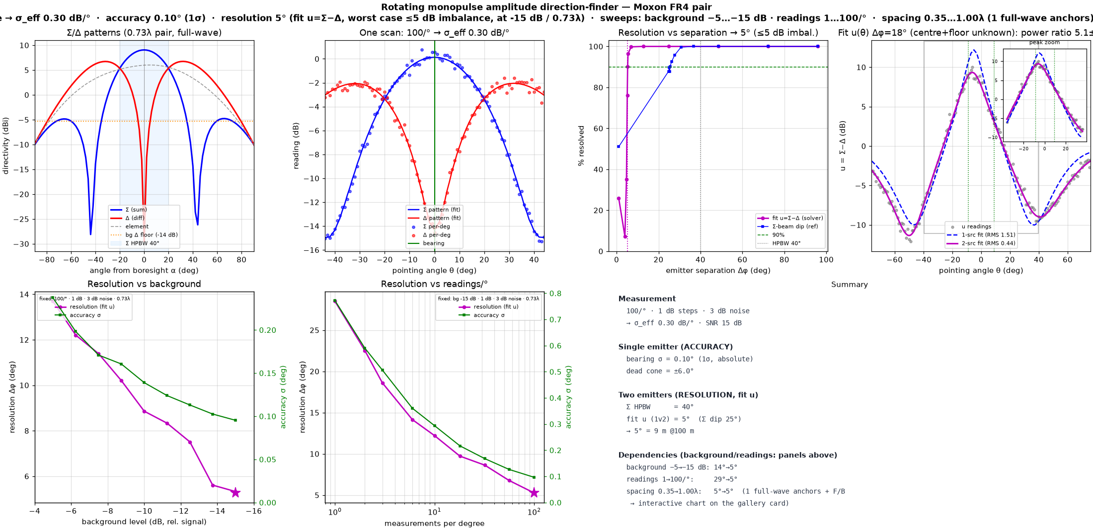
Monopulse amplitude DF — Moxon FR4 pair
ROTATING monopulse (log Σ/Δ amplitudes, no phase) → absolute bearing, no sign ambiguity · measurement: 100 readings/°, 1 dB detector steps, 3 dB noise (dither) → σ_eff 0.30 dB per 1° reading · single-emitter ACCURACY 0.10° (1σ) · two-emitter RESOLUTION 5.3° for UNEQUAL emitters (WORST case within 5 dB), decided by a 1-SOURCE GOODNESS-OF-FIT of u=Σ−Δ with the single-source null free in bearing (resolved when NO single source explains the scan, CFAR 5%) — below the 40° Σ beamwidth · resolution depends on: background −5→−15 dB ≈ 14°→5.3° · readings 1→100/° ≈ 29°→5.3° (strong; accuracy 0.8°→0.1°) · single 0.73λ full-wave anchor (no spacing re-sim for the Moxon pair) · the −15 dB background fills both this −39 dB Moxon null and the quasi-Yagi's −25 dB null to ~−15 dB, so the deeper null buys ~no extra separability · the SAME u=Σ−Δ scan also reads out an UNEQUAL pair's power ratio: a continuous 2-source least-squares fit with the pair CENTRE left free and the noise floor taken SEPARATELY from the ROTATION MINIMUM (neither assumed known) recovers, at a resolved 18° split, power ratio 5.1±0.3 dB, centre ±0.4°, floor ±0.1 dB
⬗ stack-up: FR4 1.6 mm (εr 4.3) · 1 oz Cu (35 µm) · 2× Moxon rectangle Σ/Δ @ 240 mm (0.73λ)
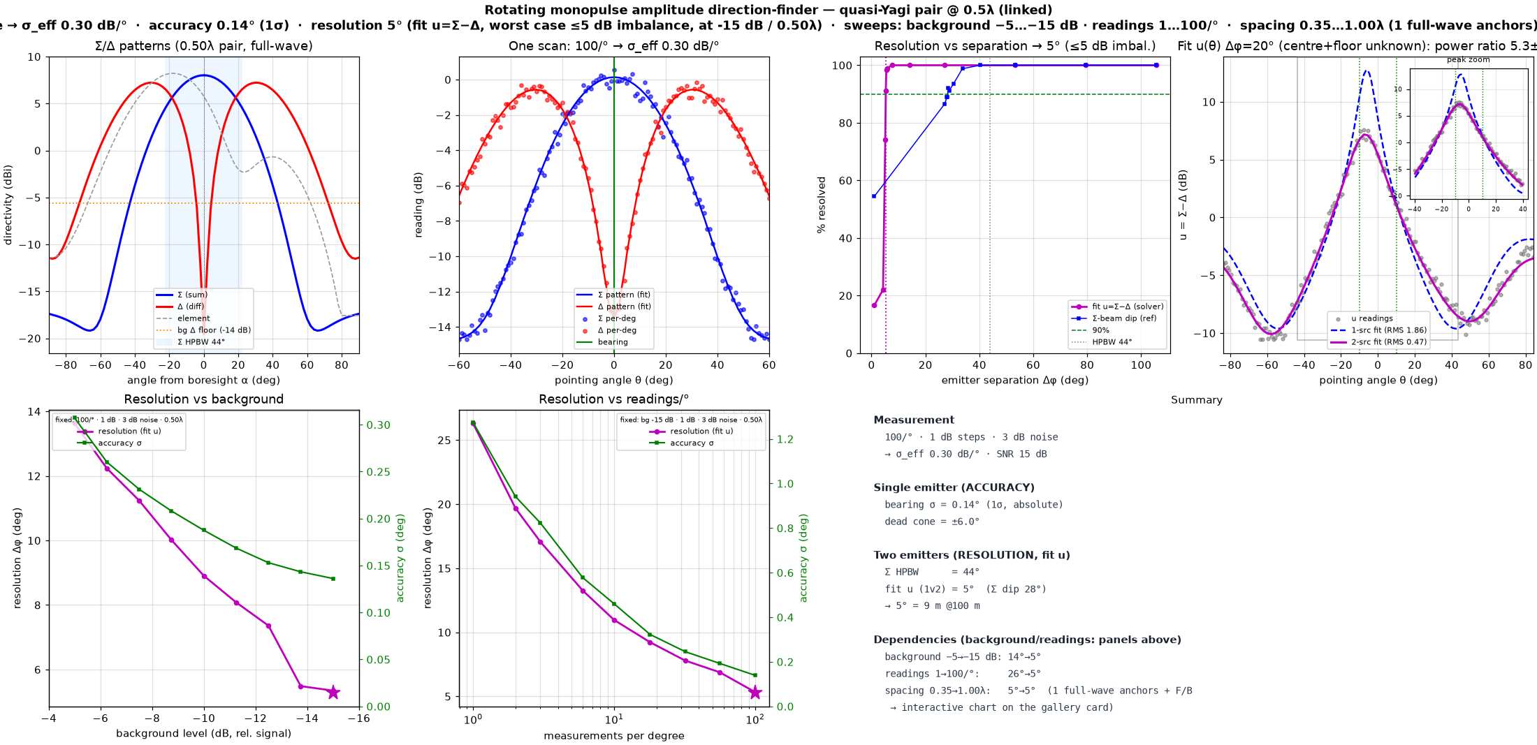
Monopulse amplitude DF — quasi-Yagi pair @ 0.5λ (linked)
FULL-WAVE gerber'd quasi-Yagi pair (uploaded-Gerber element), mechanically joined by TWO identical 12 mm × 2 mm FR4 backing splice strips on the voltage-null lines (coplanar_monopulse_linked convention), lengthened to CROSS each board's boom for a solid connection (RF-negligible): REAR across the reflectors and FRONT across the boom spine BETWEEN dir-1 and dir-2 — longitudinal field minima, off every element tip and the feed slot, so they barely move resonance/gain yet deepen the Δ null to ≈−28…−34 dB (vs −21…−25 dB unlinked), re-simulated at 0.5λ (163.9 mm) · rotating monopulse, 100 readings/° · 1 dB steps · 3 dB noise → σ_eff 0.30 dB/° · Σ HPBW 44° · Σ F/B 7.5 dB · Δ null −27.6 dB · single-emitter ACCURACY 0.14° (1σ) · two-emitter RESOLUTION 5.3° (1-source goodness-of-fit, WORST case for unequal emitters within 5 dB) · NOTE: at 0.5λ the element's 179 mm reflectors just touch/merge — the rear back-tie strip splices the two boards into one rigid panel exactly where the reflectors meet · resolution-vs-spacing = shape-preserving interpolation through 11 full-wave anchors, same design-level curve as the other cards; F/B in the 0.5–0.6λ band peaks at 8.6 dB @ 0.60λ · the u=Σ−Δ scan also reads an unequal pair's power ratio via a 2-source fit (CENTRE free + floor from the ROTATION MINIMUM): at a resolved 20° split → ratio 5.1±0.3 dB, centre ±0.4°, floor ±0.1 dB
⬗ stack-up: FR4 1.6 mm (εr 4.3) · 1 oz Cu (35 µm) · single layer · 2× 2 mm FR4 back-tie splice strips · 2-element Σ/Δ @ 163.9 mm (0.5λ)
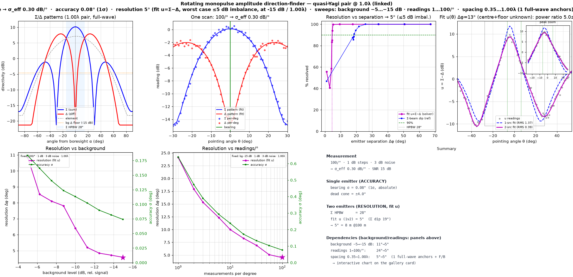
Monopulse amplitude DF — quasi-Yagi pair @ 1.0λ (linked)
FULL-WAVE gerber'd quasi-Yagi pair (uploaded-Gerber element), mechanically joined by TWO identical 12 mm × 2 mm FR4 backing splice strips on the voltage-null lines (coplanar_monopulse_linked convention), lengthened to CROSS each board's boom for a solid connection (RF-negligible): REAR across the reflectors and FRONT across the boom spine BETWEEN dir-1 and dir-2 — longitudinal field minima, off every element tip and the feed slot, so they barely move resonance/gain yet deepen the Δ null to ≈−28…−34 dB (vs −21…−25 dB unlinked), re-simulated at 1.0λ (327.9 mm) · rotating monopulse, 100 readings/° · 1 dB steps · 3 dB noise → σ_eff 0.30 dB/° · Σ HPBW 28° (narrowest of the three) · Σ F/B 7.7 dB · Δ null −31.5 dB · single-emitter ACCURACY 0.08° (1σ) · two-emitter RESOLUTION 4.6° (1-source goodness-of-fit, WORST case for unequal emitters within 5 dB) — finest, BUT the Σ pattern now has GRATING LOBES (spatial aliasing at 1λ) → ambiguous bearing · resolution-vs-spacing = shape-preserving interpolation through 11 full-wave anchors; the 1.15λ point already sits in the shaded grating region · F/B in the 0.5–0.6λ band peaks at 8.6 dB @ 0.60λ · the u=Σ−Δ scan also reads an unequal pair's power ratio via a 2-source fit (CENTRE free + floor from the ROTATION MINIMUM): at a resolved 13° split → ratio 4.9±0.3 dB, centre ±0.3°, floor ±0.1 dB
⬗ stack-up: FR4 1.6 mm (εr 4.3) · 1 oz Cu (35 µm) · single layer · 2× 2 mm FR4 back-tie splice strips · 2-element Σ/Δ @ 327.9 mm (1.0λ)
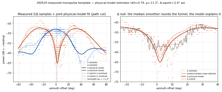
Measured Σ/Δ gain template + physical-model estimator (260529 run)
az₀ +1.4°±1.4° · el boresight ±6° (SOFT — shallow H-plane sampling) · d/λ 0.72–0.79 (design 0.73) · elem E/H HPBW 65°/94° · mount roll −11° · Δ-squint −2.6° · pass-blocked CV Σ/Δ 2.09/2.25 dB (best of 6 estimators)
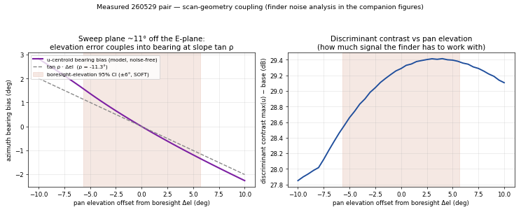
Rotating DF on the MEASURED antenna — scan 11° off the E-plane (260529 template)
measured ops (1 dB noise, 1 rdg/°, bg −12.4 dB): bearing σ 0.37° + ±1.1° SYSTEMATIC (E-plane tilt × soft elevation) · resolution 14° ≈ 25 m @100 m · reference ops: 0.09° / 5.1° ≈ the theoretical card — the gap is operations, not hardware · Σ HPBW 34° · Δ@Σ-peak −14.5 dB (squint −2.6°)
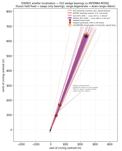
Emitter localisation on a real flight (f260601): current wedges vs antenna-model — INTERACTIVE
14 circling rotations, fusion held fixed → swaps only bearings · model removes the Σ/Δ squint bias & halves bearing scatter (σ 3.7°→2.3°) → 95% HDR cross-range 327→280 m, area 1.09→0.91 km² · range geometry-degenerate (297 m baseline, bearings 11–27°) → 5–6 km down-range ribbon for BOTH; shipped mesh vs grid peaks disagree 764 m
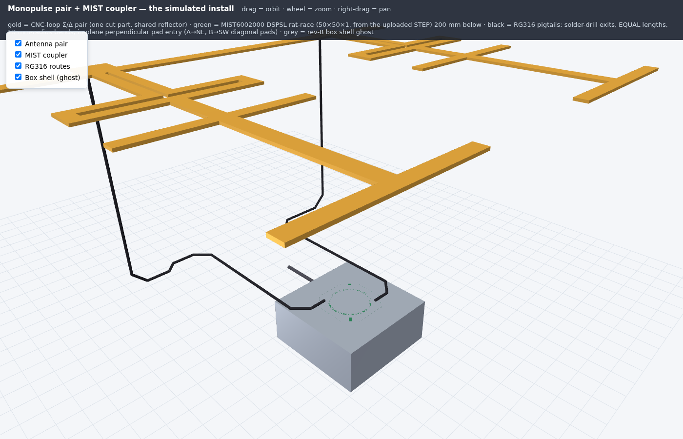
Monopulse pair + real MIST coupler — the simulated install
The full DF front-end as SIMULATED, end to end: CNC-loop Σ/Δ pair (0.73λ, shared reflector) with the user's MIST6002000 coupler — 50×50×1 DSPSL rat-race with via-swap 180° inverter, extracted from the uploaded CST STEP — 200 mm below the antenna plane, fed by build-faithful RG316 pigtails (exits at the elements' solder pass-drills, EQUAL lengths via auto-sized service jog, 13 mm bend radius, in-plane perpendicular entry at the diagonal A/NE & B/SW pads) · COUPLER validated as-drawn (0.1 mm-mesh openEMS): at 915 on FR4 4.3 RL −20.5/−21.5 dB, split imbalance 0.27 dB, phase error 1.5°/1.6°, Σ↔Δ isolation −39 dB; laminate fit εr 3.90→4.65 leaves balance/phase/iso FLAT (topology-set) — build on ordinary 1.0 mm FR4; radiation efficiency −36.5 dB (self-shielding DSPSL: direct pickup ≈44 dB below the antenna path bare, unmeasurable boxed) · INSTALL patterns (MUR): pair alone Σ 11.5 dBi / F/B 13.0 / Δ null 41.5 dB → with cables 34.3 → + bare coupler 31.3 (Σ F/B 7.3 — the horizontal runs act as a weak back-reflector) → full boxed install 28.9 dB null, Σ tilt +8° (calibrate or pre-tilt); every build ≥14 dB above the −15 dB DF background floor · BOX SIZING for movability (4 sizes × 4 positions): the 60×60×30 coupler-only box wins every column (Σ tilt −6…0° wherever it sits, vs −12…+14° for the 95×95×41.5 rev-B) — fix the big box or shrink it to move it · plane-wave ingress: sealed gland = zero in all orientations; snug unbonded hole −67 dB vs antenna worst-case; worst pol = E along cable · interactive 3D below (toggle pair / coupler / cables / box)
⬗ stack-up: FR4 2 mm CNC pair (one cut part) · MIST6002000 DSPSL coupler 50×50×1 on FR4 1.0 · RG316 equal-length routes · rev-B wrapped box (or 60×60×30 coupler-only) · openEMS on Modal
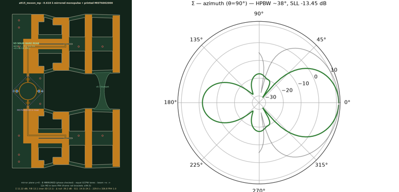
Monopulse Σ/Δ board — mirrored moxon pair + printed MIST coupler, SMA on the pads
ONE 2-layer FR4 1.0 mm board (229 × 327 mm): two a915_moxon 4-el quasi-Yagis at 200 mm (0.610 λ) with the user's MIST6002000 DSPSL rat-race PRINTED between the reflectors, fed on-board, Σ/Δ SMA jacks mounted PERPENDICULAR directly on the coupler pads · SYMMETRY (user-directed): antenna B is MIRRORED (not translated), so the board has a true mirror plane at y=0 — the two off-centre a915 feeds land symmetric at |y|=100, the coupler sits centred, and the two straight GCPW lanes are exactly equal (69.8 mm); FR4 outline + all copper mirror to 0.0 mm² except the MIST's own via-swap inverter arm (1.4 mm², inherent) · the MIST is printed as-extracted but ROTATED 45° so its pads land on compass points — A=N, B=S, Σ=W, Δ=E; PHASE checked (not assumed): because the moxon feed slot straddles the element centreline, mirroring preserves the feed phase, so Σ (in-phase) still drives the SUM beam and Δ (180°) the NULL — no role swap · the SMA pins drill through the Σ/Δ pad centres, the 4 flange legs solder into the coupler's own bottom pads (the DSPSL return); coupler plate merges into the V3 SOLID BARE REAR: uncoppered FR4 from the reflector apron (x=10.5) back to the plate rear line (x=−29.5) over each antenna's full y — pockets filled, board rear is ONE straight edge · COUPLER validated as-rotated (openEMS, 0.1 mm mesh, ports at the pads): every port matched −22…−24 dB, equal 3 dB splits (imbalance 0.04 dB), Σ splits in-phase (−1.5°) / Δ 180° (+178°), Σ↔Δ isolation −39 dB · ANTENNA pair (PML_8, 200 mm, V3 rear): Σ 11.22 dBi, HPBW 38°, F/B 13.1 dB (worst-rear-3D lobe 13.1 — the φ180 lobe is the global rear max); Δ boresight null −39.2 dB below the 9.0 dBi difference lobes · SYSTEM (validated coupler ∘ pair): Σ 11.22 dBi / F/B 13.1, Δ null 35.3 dB below lobes, system S11 −19.4 (Σ) / −18.4 (Δ), Σ↔Δ iso −37.7 dB, coupler excess loss 0.19 dB / phase error 1.5° · DOES THE PRINTED COUPLER HURT THE ANTENNAS? measured with vs without the coupler copper: Σ gain −0.02 dB, Δ null +0.01 dB (unchanged), and F/B actually +1.4 dB (the copper is a mild back-shield) — the DSPSL is self-shielding, nearly invisible to the array · COUPLER-AS-ANTENNA (direct pickup, PML+NF2FF): it radiates only 0.027 % of its port power (−35.6 dB), worst-direction realized gain −33.1 dBi (peak up-and-off-axis at el +66°) — 44 dB below the array feedline path in its worst direction, 58 dB below along the beam, so direct pickup can't corrupt the monopulse · V0↔V3 OVERLAY (on the card): board outlines, Σ/Δ azimuth patterns, Γ(f) and the metrics table for BOTH variants side by side — V0 (chamfered plate, no rear fill: F/B 12.60, null −39.2, Γ −14.8) vs the SHIPPED V3 (F/B 13.10, null −39.2, Γ −14.5); Σ main beams overlay exactly, the difference lives in the rear shoulders · V3 REAR (user-driven A/B, PML): the solid BARE rear fill buys +0.47 dB Σ F/B FREE (dielectric drags the reflector a few MHz down the null skirt; MUR +0.49 confirms boundary-independence) while the coppered variants LOSE — V2′ screen −2.8 dB vs V3 un-retuned, and even given its fair shot (full l_refl re-tune curve 111→145, knee ~13.0 MUR at lr≈141) the re-tuned screen tops out at PML F/B 12.52 / rear-3D 12.37 vs V3's 13.10/13.10: deep-plate detuning beats screen action at 0.12 λ, and the screen moves the worst rear lobe OFF-axis — Δ null, gain, match unchanged · v0.7 TRUMPET front link (from the twin session, <1% electrical) ties the wings; mounting = 4× Ø3 NPTH in bare FR4 (plate 30,±27 + rear band 2,±150), no tabs · fab zip parses clean (gerbonara)
⬗ stack-up: FR4 1.0 mm (εr 4.3, the coupler's validated stackup) · 1 oz Cu · 2-layer via-stitched · mirrored moxon pair (mirror plane y=0) · MIST6002000 DSPSL coupler printed + rotated 45° between the reflectors · coppered arm-strip link · straight equal GCPW lanes on the coupler pads · Σ/Δ flange SMA (bottom face) · openEMS on Modal
Monopulse
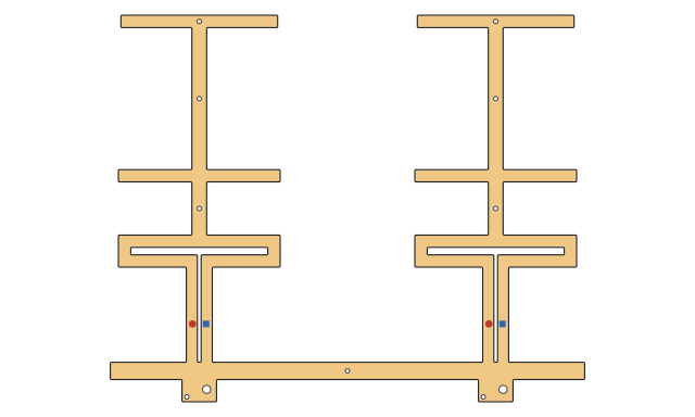
Monopulse Σ/Δ pair — TWO wide-element loop Yagis as ONE cut part (shared reflector, dual-tap)
PML_8 @915: Σ 10.5 dBi · F/B 13.8 dB · F/SLL 13.8 dB az (rear-limited; laterals lower) · worst 3D lobe −4.4 dBc (polar elevation lobes — see the finals) · S11ₐ −16.8 · BW₁₀ 43.5 MHz · Δ null 59 dB below the ±26° lobes bare (next Δ lobe 8.6 dB down), held at both ISM edges; parked-cable dress measured: identical routing 45 dB / mirrored 53 dB (MUR A/B) — still comparator-limited · ONE cut part 323×384 mm · feeds 240 mm apart (0.73λ) · 2× RG-402 → 180° hybrid
⬗ stack-up: copper-clad FR4 2.0 mm · ONE part CUT to the copper outline (laser or Ø2 mm route bit, drills Ø2) · FAT elements · dual tap drills (50/46) · 2× RG-402 pigtail → 180° hybrid
Monopulse Σ/Δ pair, THIN elements — the same pair cut with the narrow element
The gain-corner element in the pair, measured against the FAT pair at identical settings (PML_8 @915, 240 mm = 0.73λ, shared reflector link): Σ 11.1 dBi (+0.6 on FAT's 10.5 — the element's +1.4 dB does NOT all survive the array) · Σ HPBW 33° vs 32° · F/B 9.2 dB (FAT 13.8) · S11ₐ −17.8 (FAT −19.6) · Δ null 62.8 dB below the ±26° lobes, slightly DEEPER than the FAT pair's 59.2 · Δ lobes 8.8 dBi (FAT 7.1) · monopulse sensitivity is a tie: Δ/Σ = −20.9 dB at 2° and −12.5 at 5° (FAT −21.4 / −13.3), ratio slope 2.80 dB/° vs 2.69 · DF resolution is a tie too: SRL 11.4 vs 11.7° at a −5 dB background, inside the engine's ~0.24° Monte-Carlo floor · CORRECTION (2026-07-25): the first run of this pair reported a 43.8 dB null and a −1.13 dB Δ imbalance at ±2°, published here as a possible boresight bias with the cause flagged as not isolated. It was NUMERICAL. The pair seeded each element's y-mesh from its lower edge, so with this element's 131 mm driven length (half 65.5, not a multiple of the 4 mm step) side A's lines centred on +118.5 and side B's on −121.5 — a grid that is not mirror-symmetric about y=0, which fills an odd-mode null. Seeding outward from each element centre fixes it: the Δ cut is now left/right identical to 0.000 dB at every angle and the null lands at 62.8 dB. The FAT preset (half 64) happened to land symmetric, so its published results were never affected — verified by reproducing its line set exactly · so the narrow element costs NOTHING in the pair beyond F/B and bandwidth, and buys +0.6 dB Σ and no resolution · ONE cut part 313×384 mm
⬗ stack-up: copper-clad FR4 2.0 mm · ONE part CUT to the copper outline (laser or Ø2 mm route bit, drills Ø2) · THIN elements · 2× coax → 180° hybrid