Interactive 3D model — auto-rotates, drag to orbit
Statistical resolution limit (SRL) — closest two targets tellable apart vs SNR · hover a point (session 014z DF model)
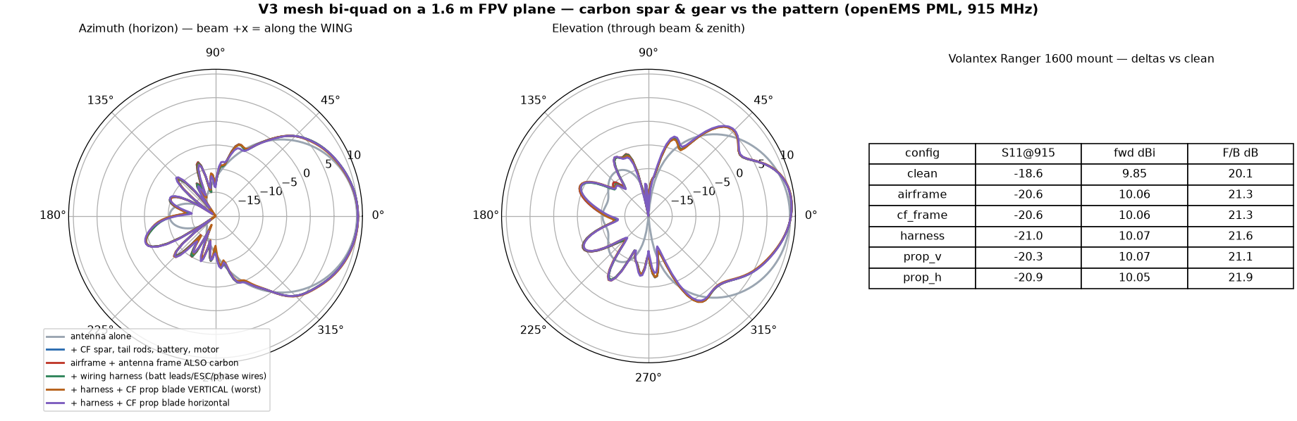
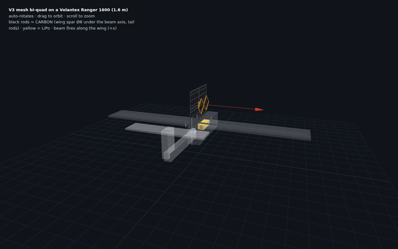
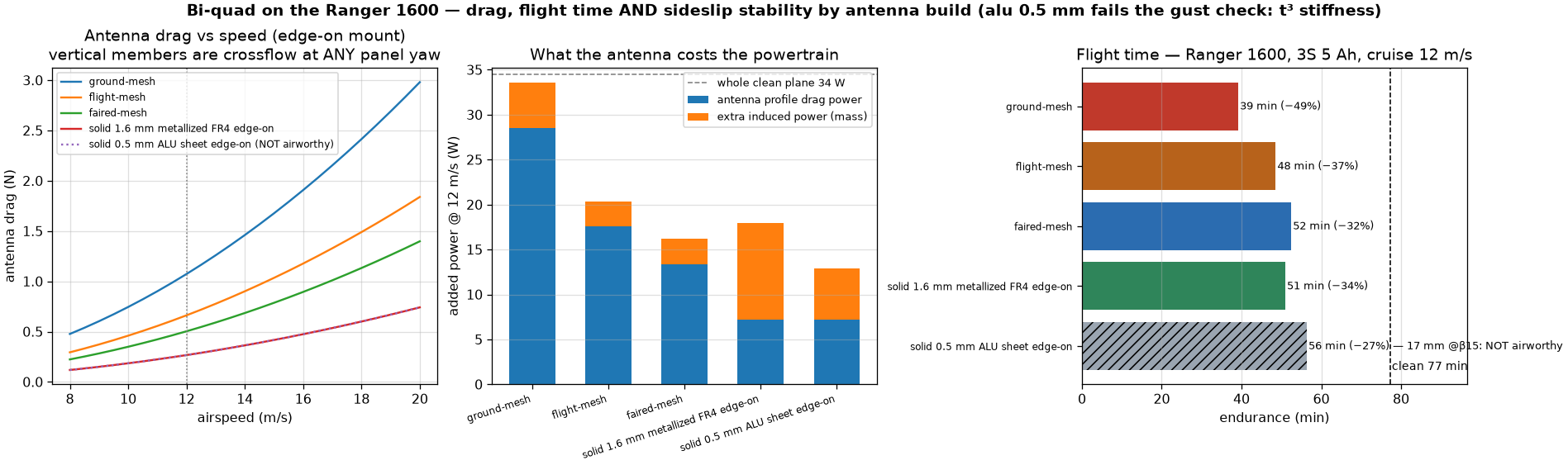
V3 mesh bi-quad vertical on the fuselage deck of a Volantex Ranger 1600 (1.6 m span, 1.1 m EPO fuselage, 1050 g AUW), plate edge-on to flight, beam along the wing · EPO foam is RF-transparent — modelled the CONDUCTORS: Ø8 CF wing spar (runs ALONG THE BEAM 40 mm below the frame), 2× CF tail rods, LiPo, pusher motor (openEMS PML, 16M cells) · EFFECT: main lobe unchanged (fwd 9.85→10.06 dBi, +0.2), F/B 20.1→21.3, match unchanged — the damage is back/side RIPPLE (±2-3 dB scalloping −5..−15 dB region) from spar scattering · antenna frame built from CARBON tube instead of steel: Δpattern < 0.09 dB everywhere (CF skin depth 0.1 mm @915 = good conductor) → frame+spine in CF solves the mass problem: Ø8 steel 0.71 kg → CF 0.04 kg; whole antenna ~160 g with Ø2 alu mesh wires (~15% AUW) · FLIGHT-TIME COST (member-sum drag + induced-drag-of-mass, 3S 5 Ah, cruise 12 m/s, clean endurance 77 min): ground-spec mesh 1.07 N → 39 min (−49%!); flight-spec (Ø1.5 wires, Ø5 CF frame, no spine — deck mount doesn't need the mast stiffening) 0.66 N → 49 min (−37%); + rod fairings 0.50 N → 52 min; 0.5 mm alu sheet posts 56 min BUT FAILS the β=15° gust check (t³ stiffness: 9.5× floppier than FR4 1.6 → ~17 mm corner flap @18 m/s, flutter risk, and no solderable face for the collar bond) · RECOMMENDED AIRBORNE BUILD: the original 1.6 mm metallized-FR4 plate edge-on — 0.27 N, 51 min (−34%), 1.8 mm @β=15° gust, solderable copper, proven V1 tuning · edge-on flight still INVERTS mesh-vs-solid drag (vertical mesh wires are crossflow cylinders at any yaw; a plate shows only its 3 mm edge) · flight-mesh (Ø1.5/Ø5 CF) = 49 min with 5× lower gust loads if rough air dominates · mount over the CG, beam points sideways — reflector shields the airframe · ROTATING 3D MODEL embedded below (drag to orbit) · EMITTER for flight: the wired element resonates ~180 Hz on its centre stub — inside the pusher-prop band (133–200 Hz @ 8–12k RPM, prop 20 cm behind) → solder-joint fatigue risk; use the PCB emitter: 0.8 mm FR4 board (43 g vs 108 g @1.6 mm), retuned side 78 @ spacing 46 → S11 −31 dB @917, realized 10.27 dBi (η 98% — thinner FR4 is LOWER loss), centre coax bond acts as 5th support lifting board modes above the prop band · SPACERS: keep NYLON standoffs deliberately — axial (spacing) mode ~550 Hz (RF dim rock-solid), lateral sway ~25–40 Hz = vibration ISOLATION below the prop band; aluminium/steel standoffs land AT 125–190 Hz, inside it · nyloc hardware (nylon posts loosen), optional teardrop fairings halve the ~0.11 N spacer drag · MOTOR-SYSTEM FOLLOW-UP (the motor BODY was always in the sim — a PEC block at the pod rear; now added the conductors around it): WIRING HARNESS (batt leads/ESC/phase wires, 25 cm strip) — negligible: main lobe +0.01 dBi, worst rear-az change 0.6 dB · PROP BLADES (8" CF, worst-case static orientations vertical vs horizontal bound the spinning-blade modulation): main-lobe ripple ±0.07 dB, rear lobes up to ±1.7 dB at 2×rev-rate (~270-400 Hz sidebands, −20 dB region only), S11 swings −20.3↔−21.0 dB — the link never sees it; a metal-hub/alu prop would double the ripple, keep CF
⬗ stack-up: V3 mesh reflector (Ø2 wires @40 mm, CF Ø8 frame+spine) · 2 mm Cu element · Ranger-1600-class EPO airframe