Interactive 3D model — auto-rotates, drag to orbit
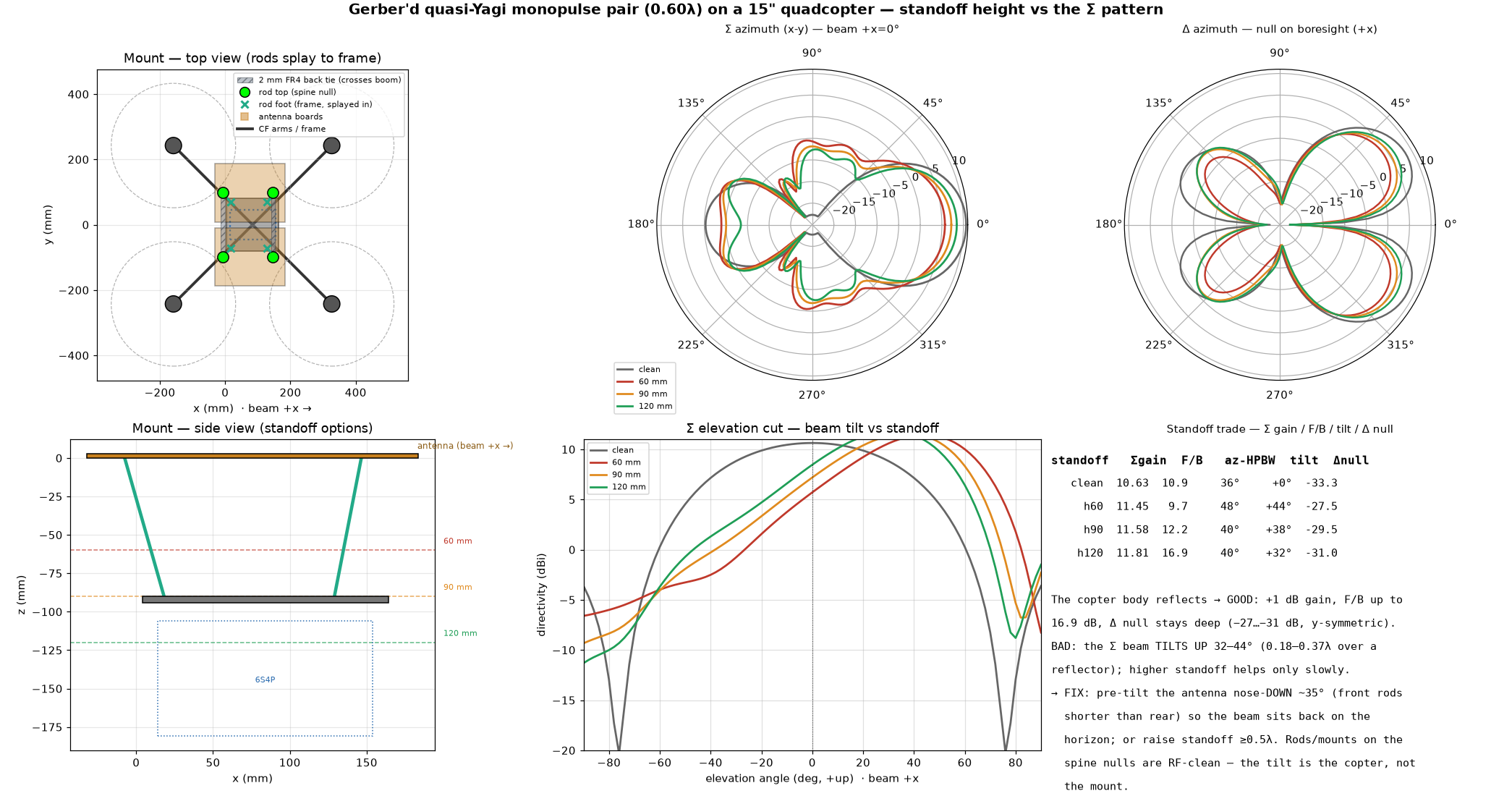
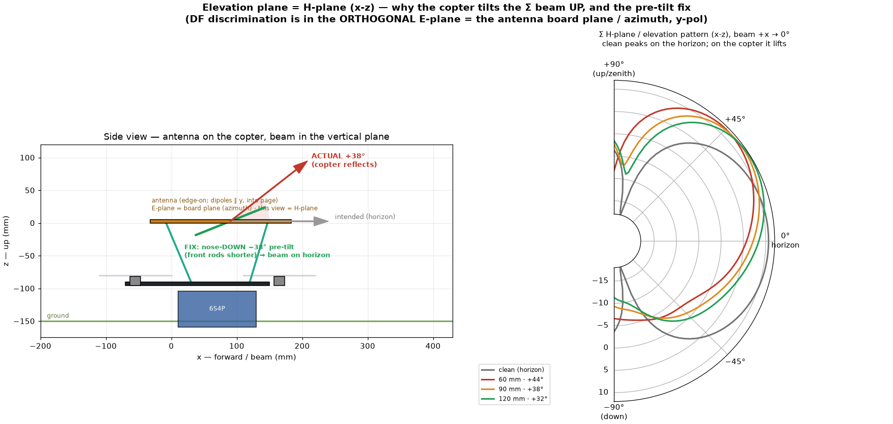
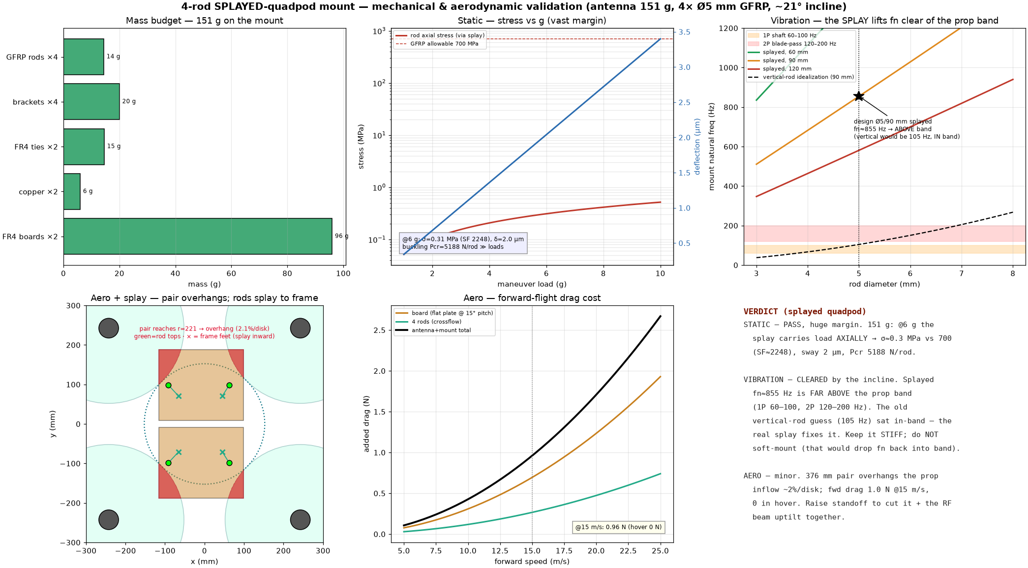
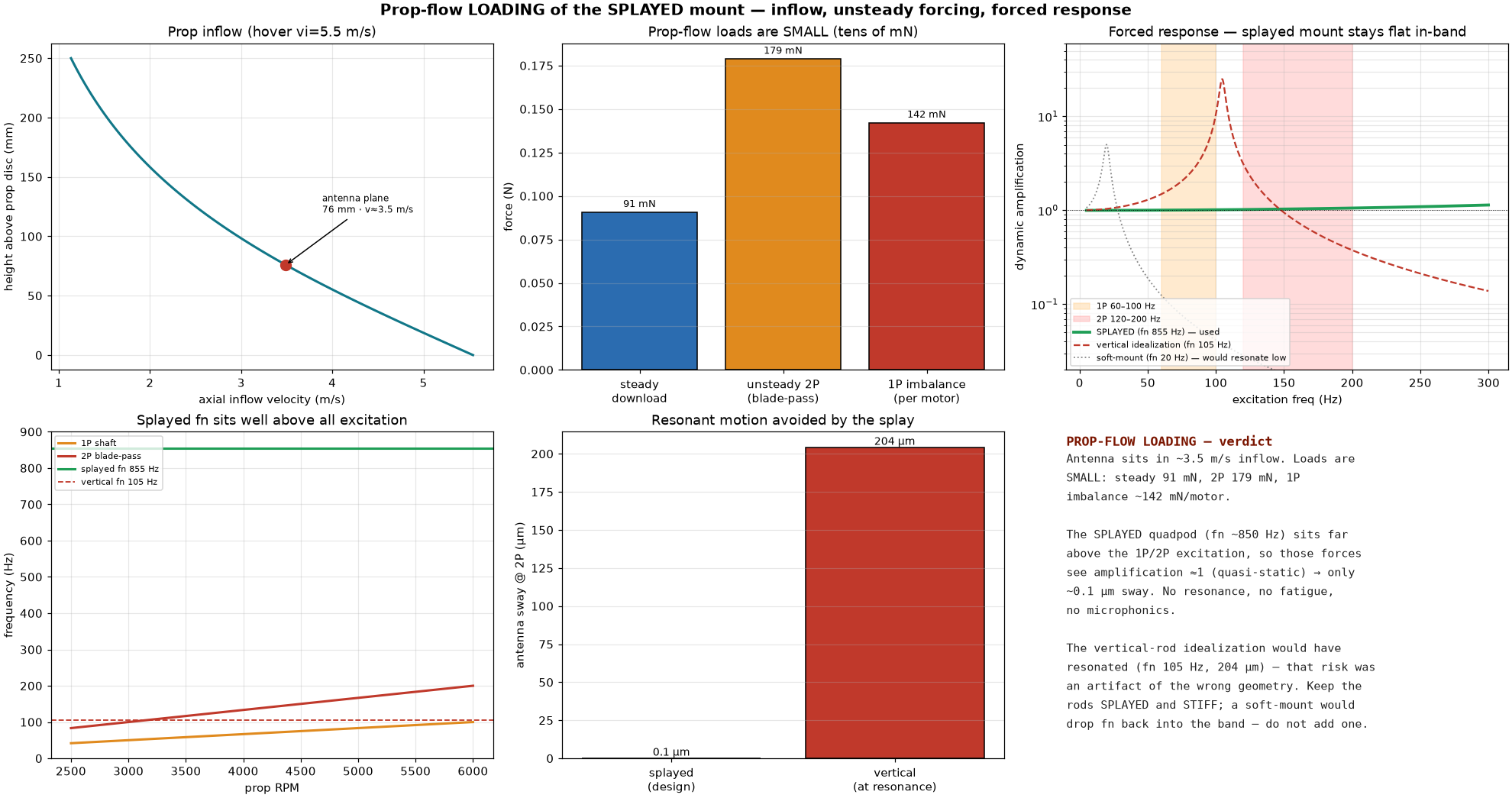
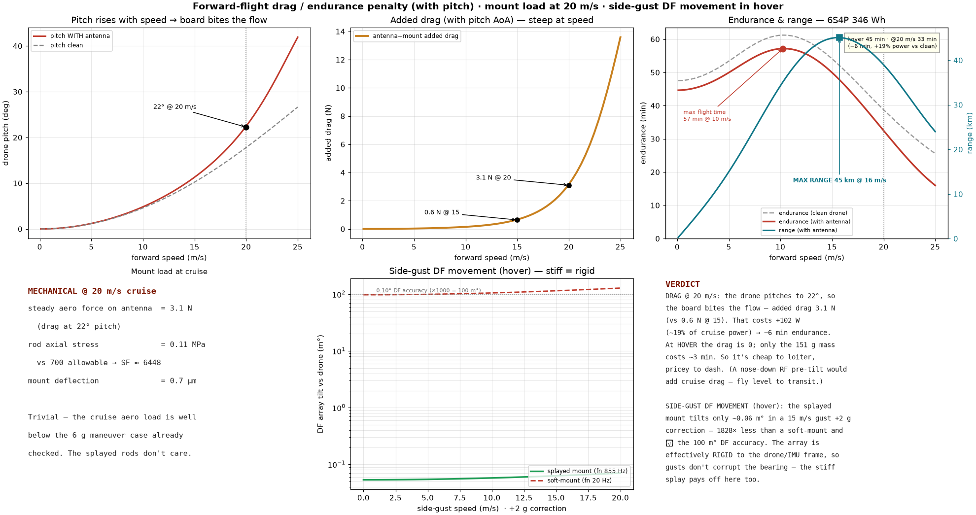
The 0.60λ (max-F/B) gerber'd quasi-Yagi Σ/Δ pair mounted FLAT ON TOP of a 15" quad (686 mm wheelbase, CF plate + 4 arms + 4 motors, 6S4P 21700 pack under) on 4× Ø5 mm GLASS-FIBRE rods that SPLAY inward (inclined quadpod) from the two boards' boom-spine VOLTAGE-NULL lines (rear reflector station x=−7.5, front dir1/dir2 gap x=146.5, y=±98.4) down to the CF plate — a wide 154×197 mm top footprint, RF-clean, each rod capped in a 3D-printed bracket screwed to the spine and glued to the rod; the two boards are spliced by TWO 12 mm × 2 mm FR4 back-ties on those same spine null lines, LENGTHENED to CROSS each board's boom so the pair is one rigid connected unit (RF-negligible, ΔΣ F/B 0.03 dB) · interactive 3D model embedded below (shows the boom-crossing ties + rod brackets) · RF (full-wave PML, standoff 60/90/120 mm vs clean): the copter body acts as an extra reflector → GOOD Σ gain +0.8…1.2 dB (→11.4–11.8 dBi), Σ F/B up to 12–17 dB, Δ null stays deep (−27…−31 dB, copter symmetric about the array axis) — BUT the Σ beam TILTS UP 44°→38°→32° over 60→120 mm (horizontal antenna 0.18–0.37λ over a reflector); FIX = nose-DOWN ~35° pre-tilt (front rods shorter) or standoff ≥0.5λ (see the ELEVATION-PLANE diagram: clean peaks on the horizon, the mounted lobe lifts to +32…+44°, and a nose-down pre-tilt rotates it back); the splayed thin rods on the null lines are RF-negligible (pattern unchanged vs no rods) · MECHANICAL (analytic, 151 g assembly): the SPLAY carries LATERAL/tilt loads AXIALLY → lateral fn ≈ 855 Hz, and even a drone bank only puts m·g·sinθ through the rods as axial (SF ≈ 2250 @6 g, buckling ~6 kN/rod). BUT a lateral-only view is incomplete: the DF-critical axis is YAW (a Δ-null twist vs the drone is a 1:1 bearing error, spec < 0.1° = 100 m°). Yaw is bending-resisted (~7× softer, ~125 Hz rigid-ideal, in the 2P band) AND — decisively — the 4 near-radial rods react ~94% out-of-plane onto the 1.6 mm board, which is ~1300× too soft there, so yaw is effectively an UNCONSTRAINED MECHANISM through the floppy PCB (skewing the feet only couples g→yaw and still pushes out-of-plane). FIX = an 8-strut DIAGONALLY-BRACED quadpod (4 rods + 4 wall diagonals, shown in the 3D with a 6/8-strut toggle): the diagonals react every node AXIALLY → stiff in all 6 DOF (lowest mode ~370 Hz, above the 2P band), so the Δ-null stays within 0.1° vs the drone under gust + brisk yaw; 8 struts are REDUNDANT/fail-safe; the BEST minimal 6 (toggle in the 3D) is an OCTAHEDRAL hexapod on a 3-POINT KINEMATIC attach along the null ties — 1 on the reflector-tie mid-span (between the boards, RF-quietest; that tie is board-backed so its free span is ~17 mm) + 2 on the dir1/dir2 tie at the boom bonds (elsewhere it spans routed windows) — base triangle anti-aligned on the plate: a yaw torque puts ZERO out-of-plane force on the board (carried in-plane, the ~90× stiffer direction), 3-point support cannot warp the boards, zero g→yaw coupling. CAVEAT the 3-pt attach leaves the reflector rear corners ~200 mm from any support → 0.66 mm/g droop flapping at 24 Hz, so the design INCLUDES a 15×5 G10 REAR SPAR (full width) + 12×6 ribs (+110 g) with RF-DRIVEN placement — FDTD @0.60λ measured a spar ALONG the reflector line costs 0.40 dB Σ F/B (near-field loading), so the spar sits at the board REAR EDGE behind the reflector copper and the ribs at the OUTER spine edge ~10 mm off the feed slot (measured cost: ΔF/B 0.05 dB, gain −0.04 dB, Δ null unchanged — negligible): coupled flexible-board model then gives board modes ≥44 Hz, sag 0.04 mm/g, yaw 715 Hz — beating the 8-strut on every stiffness number, but statically determinate = collapse on one strut/bond loss (fail-safety is the 8-strut's case). Splitting the rear attach into two (4-pt/6-strut) fixes the droop without a spar but leaks in-plane loads out-of-plane at the un-paired points (~23 Hz coupled sway); V-pairs at all four points = the 8-strut. A valid 6 must also be non-singular — 4 parallel radial rods are rank-3, not 6. Separately, the 1.6 mm FR4 element overhangs flap out-of-plane at ~106 Hz (in-band) → add a STIFFENING RIB along the elements; that flap is elevation-only (2nd-order for azimuth bearing). Prior "over-built, keep stiff, no resonance" verdict SUPERSEDED by this braced/ribbed design · PROP-FLOW loads are small (steady 73 mN, unsteady 2P 143 mN, 1P imbalance 142 mN/motor) and with fn≫excitation see ≈1× amplification → ~0.1 µm sway, no fatigue/microphonics · FLIGHT (3.5 kg AUW, 6S4P ≈346 Wh usable, FM 0.60): endurance HOVER ~45 min, MAX ~57 min @ 10 m/s (translational lift beats hover), ~33 min @ 20 m/s; MAX RANGE ~45 km @ 16 m/s; the antenna costs ~3 min at hover (mass), ~4 min/4 km at loiter/cruise, ~6 min by 20 m/s (board pitches to 22° → 3.1 N drag, +19% cruise power) · SIDE-GUST DF MOVEMENT (hover): the stiff splay tilts the array only ~0.06 m° in a 15 m/s gust +2 g correction (≪ the 100 m° DF accuracy) → the array is effectively RIGID to the drone/IMU frame, gusts don't corrupt the bearing · VERDICT: structurally + for DF-pointing stability ROBUST (over-built, off-resonance, gust-immune); the one gating item is the RF beam uptilt — commit to the nose-down pre-tilt / higher standoff and validate it, then green end-to-end · plastic props + printed brackets RF-transparent, not modelled; numbers are analytic + indicative (the mounted RF runs decayed to −23…−27 dB)
⬗ stack-up: 0.60λ Σ/Δ pair (2× routed FR4 + 2 mm FR4 back-ties) · 4× Ø5 mm glass-fibre rods SPLAYED (inclined quadpod) to a 15" CF quad · 3D-printed spine brackets · 6S4P 21700, ~3.5 kg AUW