Interactive 3D model — auto-rotates, drag to orbit
Statistical resolution limit (SRL) — closest two targets tellable apart vs SNR · hover a point (session 014z DF model)
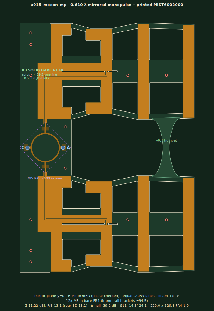
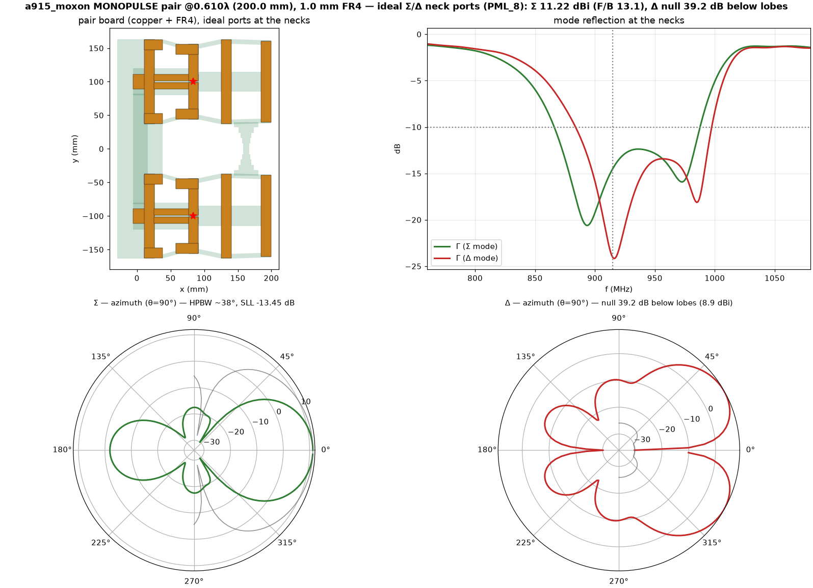
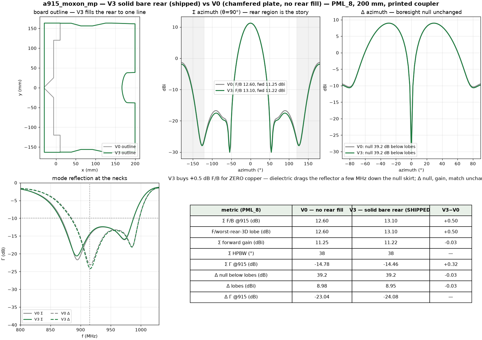
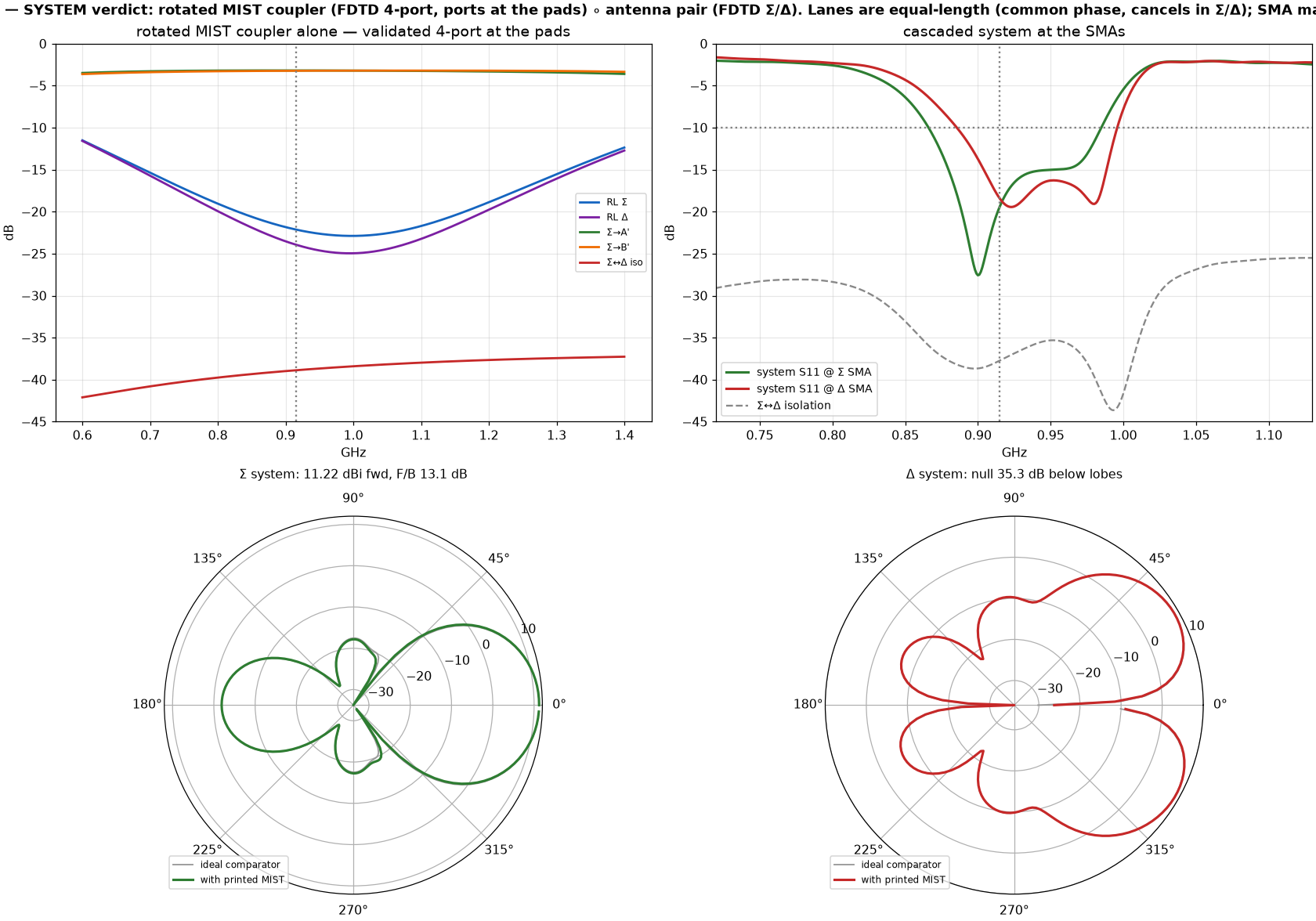
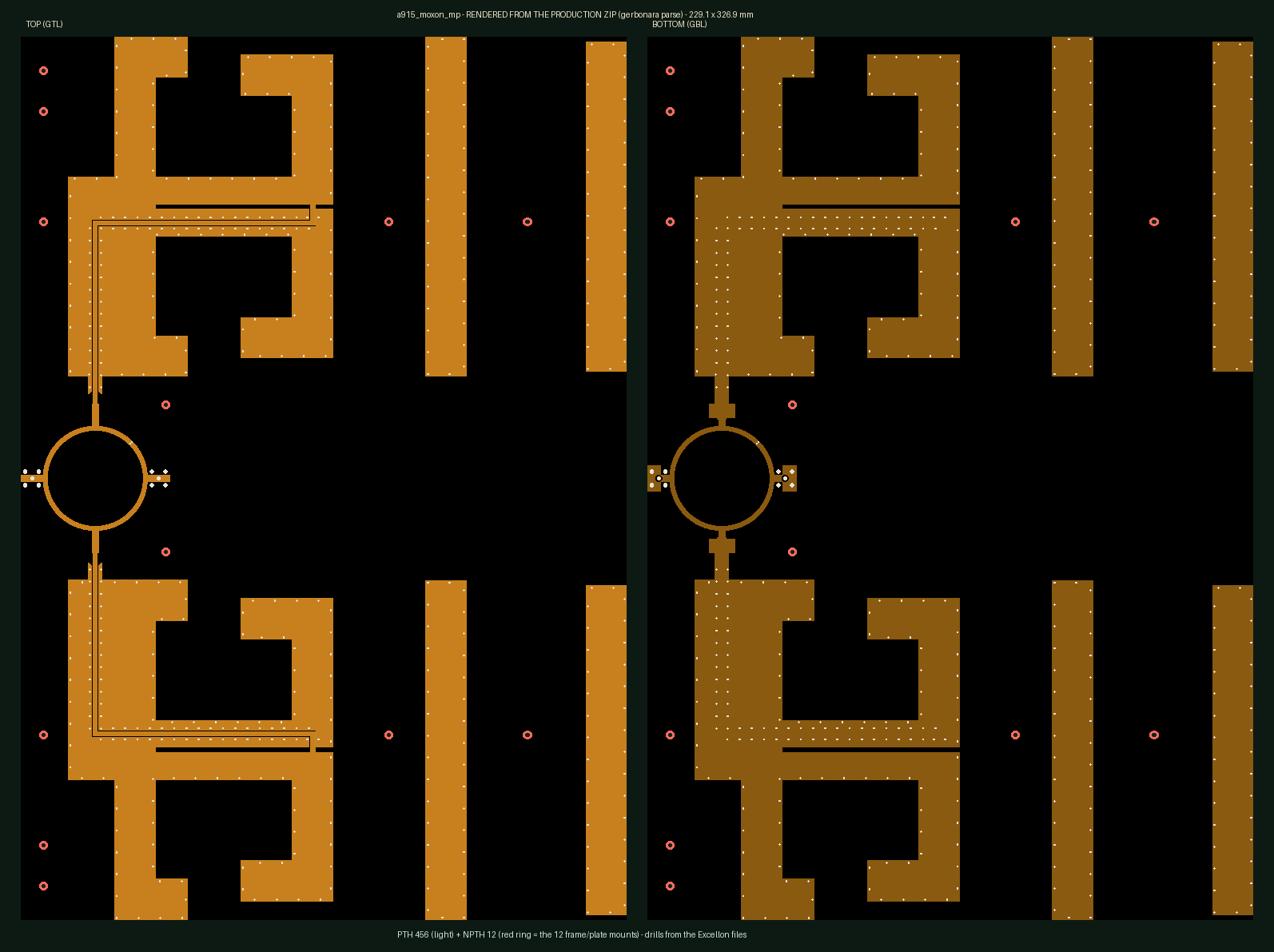
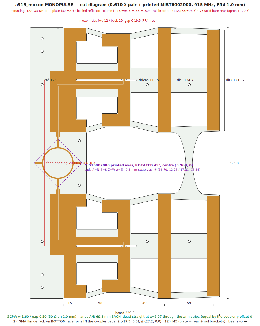
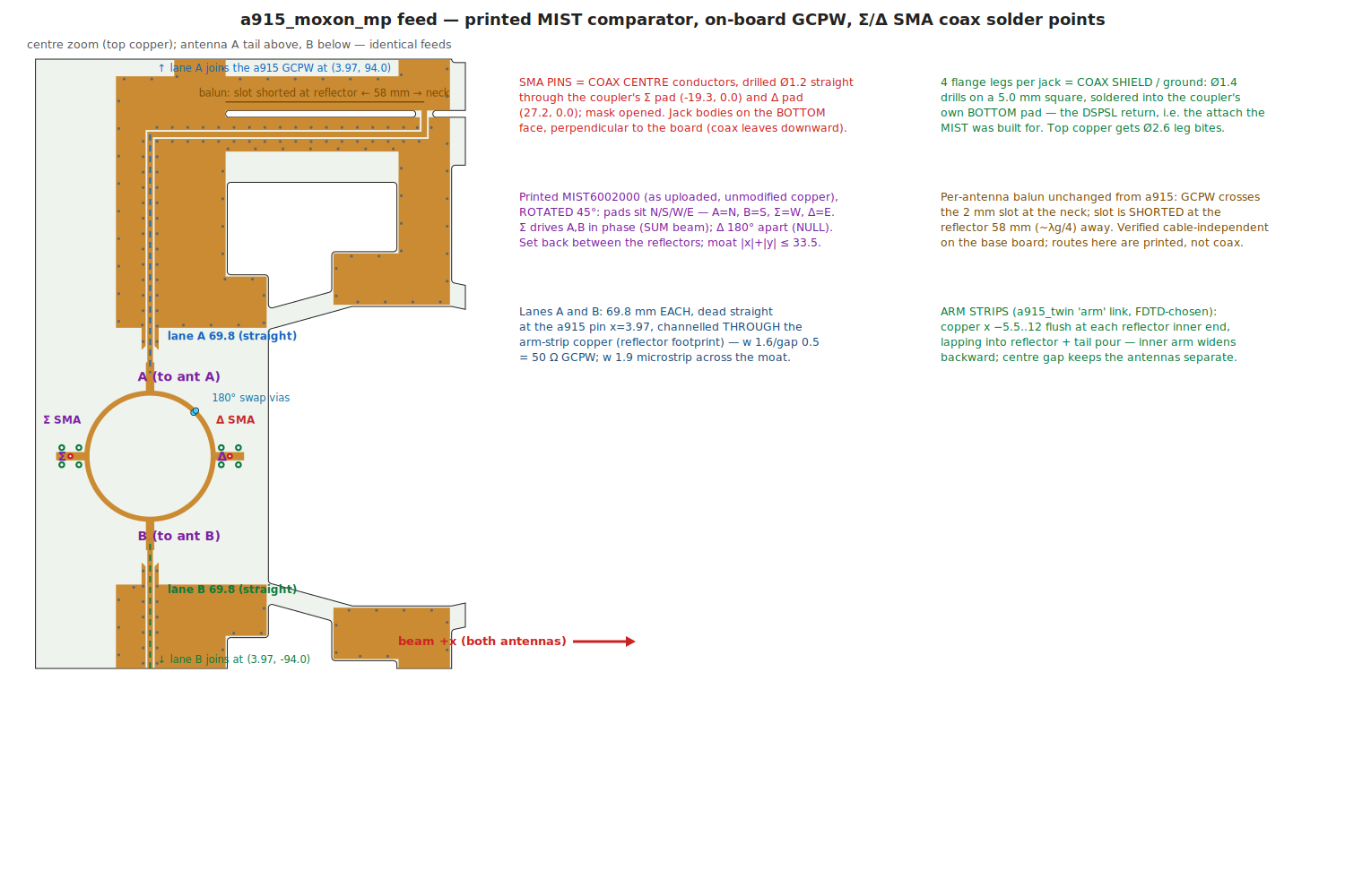
ONE 2-layer FR4 1.0 mm board (229 × 327 mm): two a915_moxon 4-el quasi-Yagis at 200 mm (0.610 λ) with the user's MIST6002000 DSPSL rat-race PRINTED between the reflectors, fed on-board, Σ/Δ SMA jacks mounted PERPENDICULAR directly on the coupler pads · SYMMETRY (user-directed): antenna B is MIRRORED (not translated), so the board has a true mirror plane at y=0 — the two off-centre a915 feeds land symmetric at |y|=100, the coupler sits centred, and the two straight GCPW lanes are exactly equal (69.8 mm); FR4 outline + all copper mirror to 0.0 mm² except the MIST's own via-swap inverter arm (1.4 mm², inherent) · the MIST is printed as-extracted but ROTATED 45° so its pads land on compass points — A=N, B=S, Σ=W, Δ=E; PHASE checked (not assumed): because the moxon feed slot straddles the element centreline, mirroring preserves the feed phase, so Σ (in-phase) still drives the SUM beam and Δ (180°) the NULL — no role swap · the SMA pins drill through the Σ/Δ pad centres, the 4 flange legs solder into the coupler's own bottom pads (the DSPSL return); coupler plate merges into the V3 SOLID BARE REAR: uncoppered FR4 from the reflector apron (x=10.5) back to the plate rear line (x=−29.5) over each antenna's full y — pockets filled, board rear is ONE straight edge · COUPLER validated as-rotated (openEMS, 0.1 mm mesh, ports at the pads): every port matched −22…−24 dB, equal 3 dB splits (imbalance 0.04 dB), Σ splits in-phase (−1.5°) / Δ 180° (+178°), Σ↔Δ isolation −39 dB · ANTENNA pair (PML_8, 200 mm, V3 rear): Σ 11.22 dBi, HPBW 38°, F/B 13.1 dB (worst-rear-3D lobe 13.1 — the φ180 lobe is the global rear max); Δ boresight null −39.2 dB below the 9.0 dBi difference lobes · SYSTEM (validated coupler ∘ pair): Σ 11.22 dBi / F/B 13.1, Δ null 35.3 dB below lobes, system S11 −19.4 (Σ) / −18.4 (Δ), Σ↔Δ iso −37.7 dB, coupler excess loss 0.19 dB / phase error 1.5° · DOES THE PRINTED COUPLER HURT THE ANTENNAS? measured with vs without the coupler copper: Σ gain −0.02 dB, Δ null +0.01 dB (unchanged), and F/B actually +1.4 dB (the copper is a mild back-shield) — the DSPSL is self-shielding, nearly invisible to the array · COUPLER-AS-ANTENNA (direct pickup, PML+NF2FF): it radiates only 0.027 % of its port power (−35.6 dB), worst-direction realized gain −33.1 dBi (peak up-and-off-axis at el +66°) — 44 dB below the array feedline path in its worst direction, 58 dB below along the beam, so direct pickup can't corrupt the monopulse · V0↔V3 OVERLAY (on the card): board outlines, Σ/Δ azimuth patterns, Γ(f) and the metrics table for BOTH variants side by side — V0 (chamfered plate, no rear fill: F/B 12.60, null −39.2, Γ −14.8) vs the SHIPPED V3 (F/B 13.10, null −39.2, Γ −14.5); Σ main beams overlay exactly, the difference lives in the rear shoulders · V3 REAR (user-driven A/B, PML): the solid BARE rear fill buys +0.47 dB Σ F/B FREE (dielectric drags the reflector a few MHz down the null skirt; MUR +0.49 confirms boundary-independence) while the coppered variants LOSE — V2′ screen −2.8 dB vs V3 un-retuned, and even given its fair shot (full l_refl re-tune curve 111→145, knee ~13.0 MUR at lr≈141) the re-tuned screen tops out at PML F/B 12.52 / rear-3D 12.37 vs V3's 13.10/13.10: deep-plate detuning beats screen action at 0.12 λ, and the screen moves the worst rear lobe OFF-axis — Δ null, gain, match unchanged · v0.7 TRUMPET front link (from the twin session, <1% electrical) ties the wings; mounting = 4× Ø3 NPTH in bare FR4 (plate 30,±27 + rear band 2,±150), no tabs · fab zip parses clean (gerbonara)
⬗ stack-up: FR4 1.0 mm (εr 4.3, the coupler's validated stackup) · 1 oz Cu · 2-layer via-stitched · mirrored moxon pair (mirror plane y=0) · MIST6002000 DSPSL coupler printed + rotated 45° between the reflectors · coppered arm-strip link · straight equal GCPW lanes on the coupler pads · Σ/Δ flange SMA (bottom face) · openEMS on Modal