4-element loop-fed Yagi, STABLE — OWA-matched, flat impedance AND pattern across the band, on any FR4
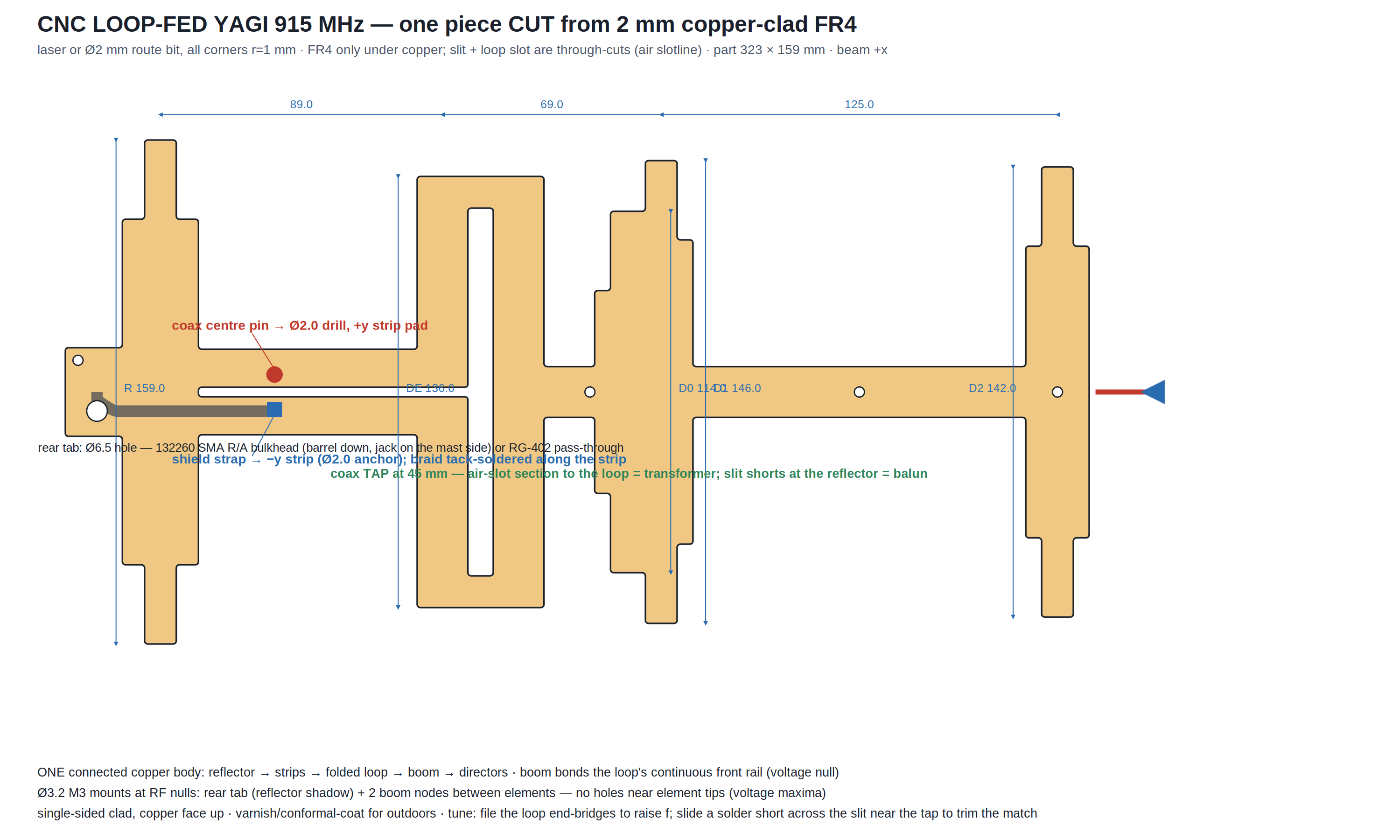
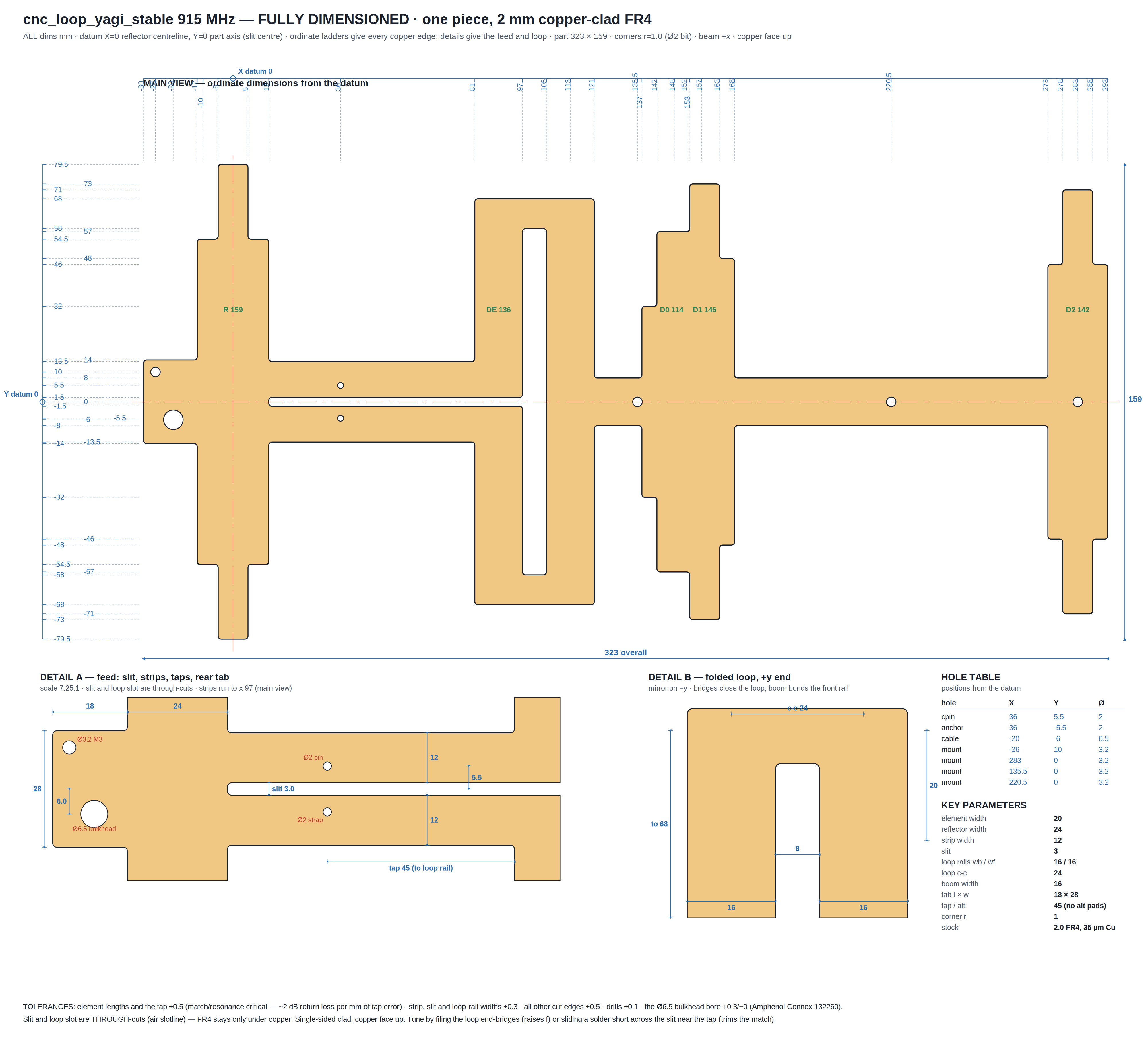
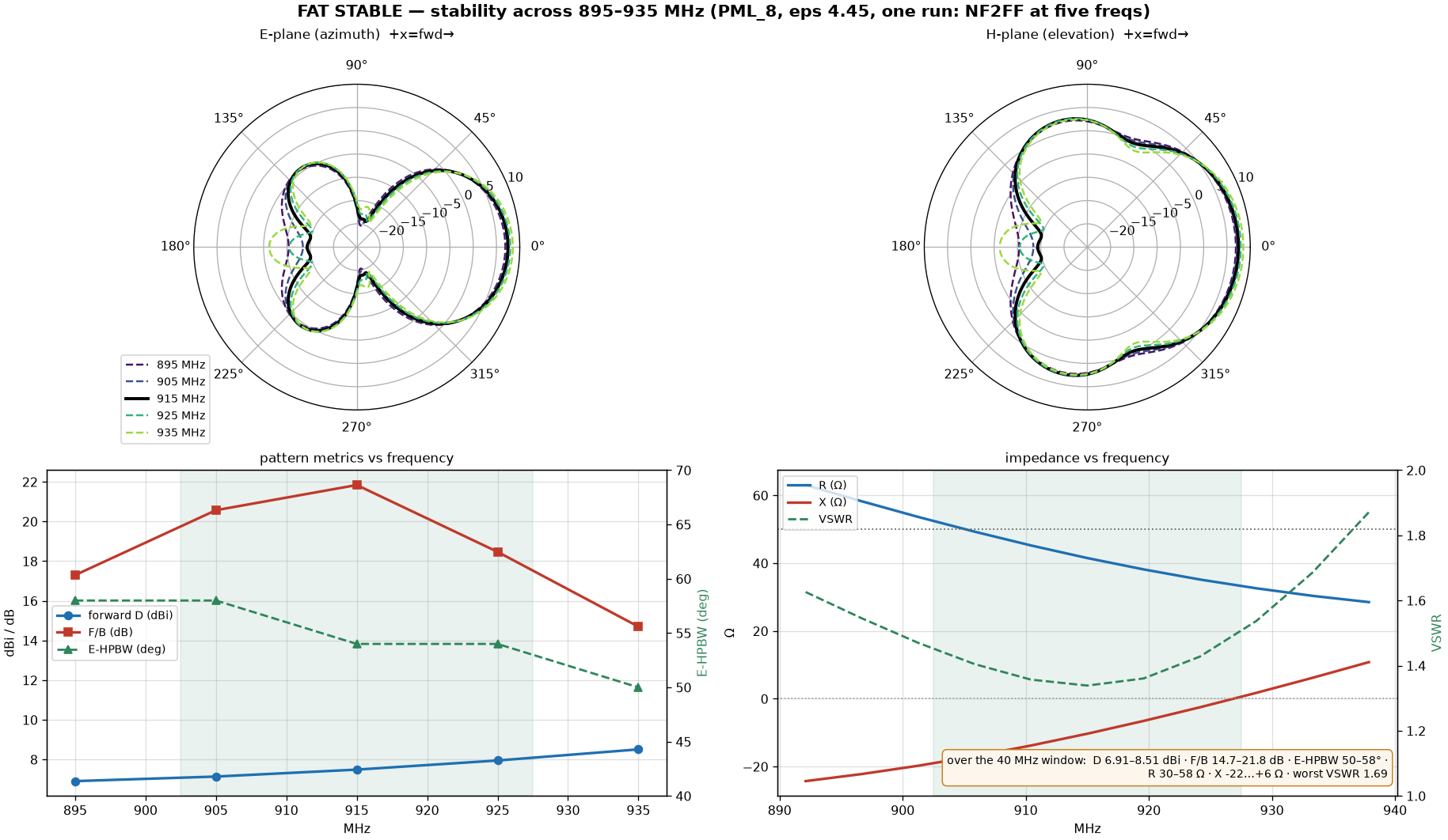
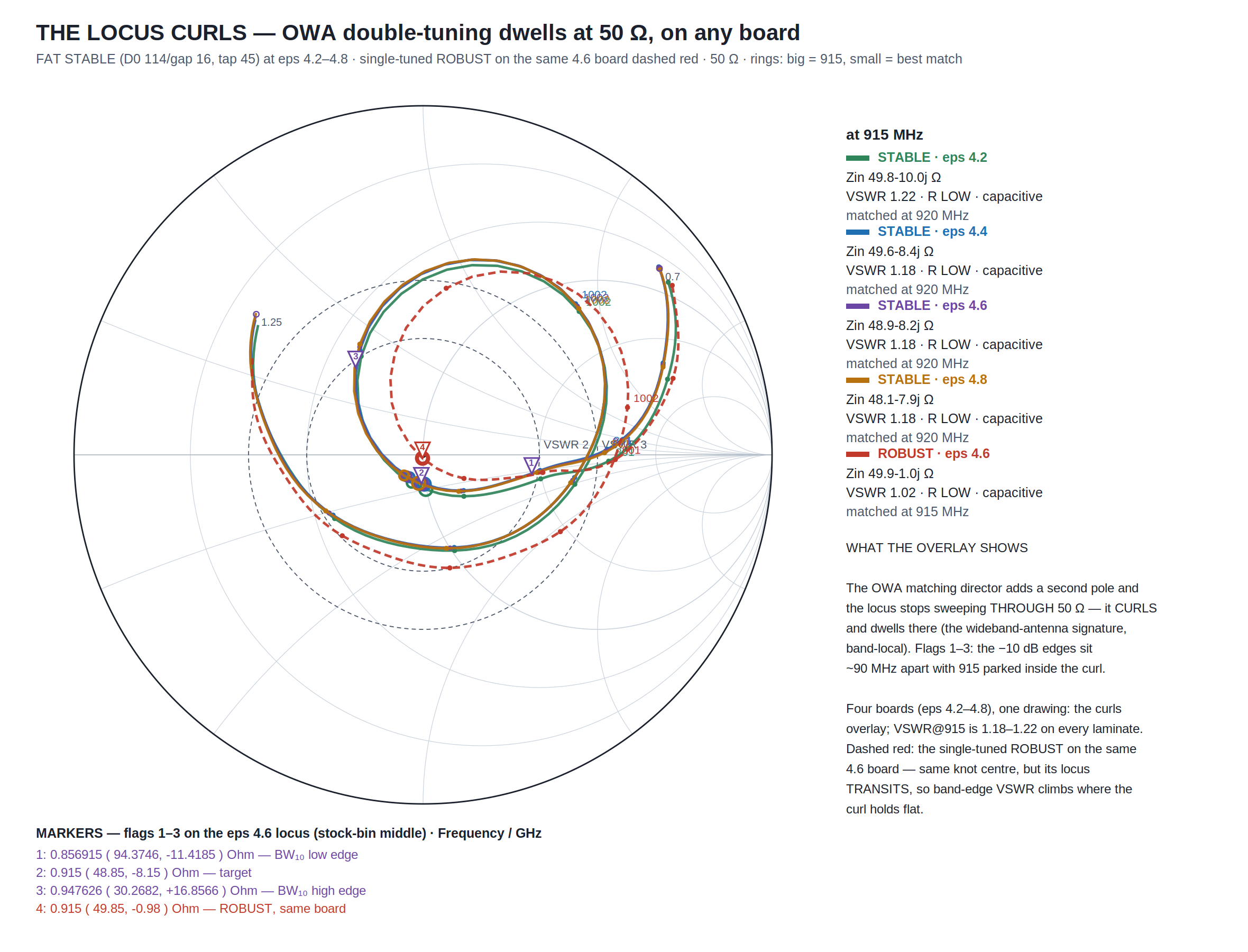
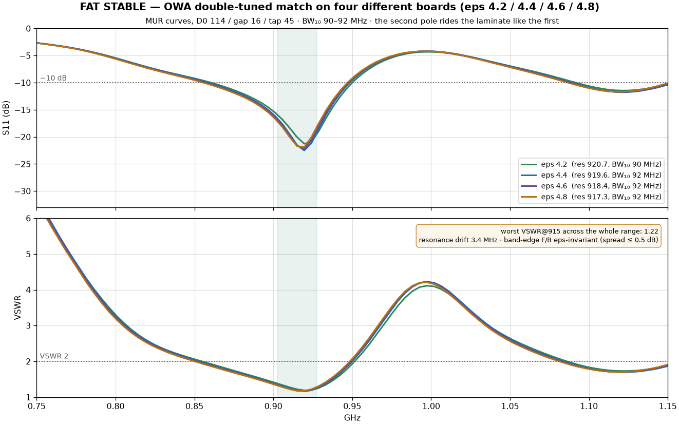
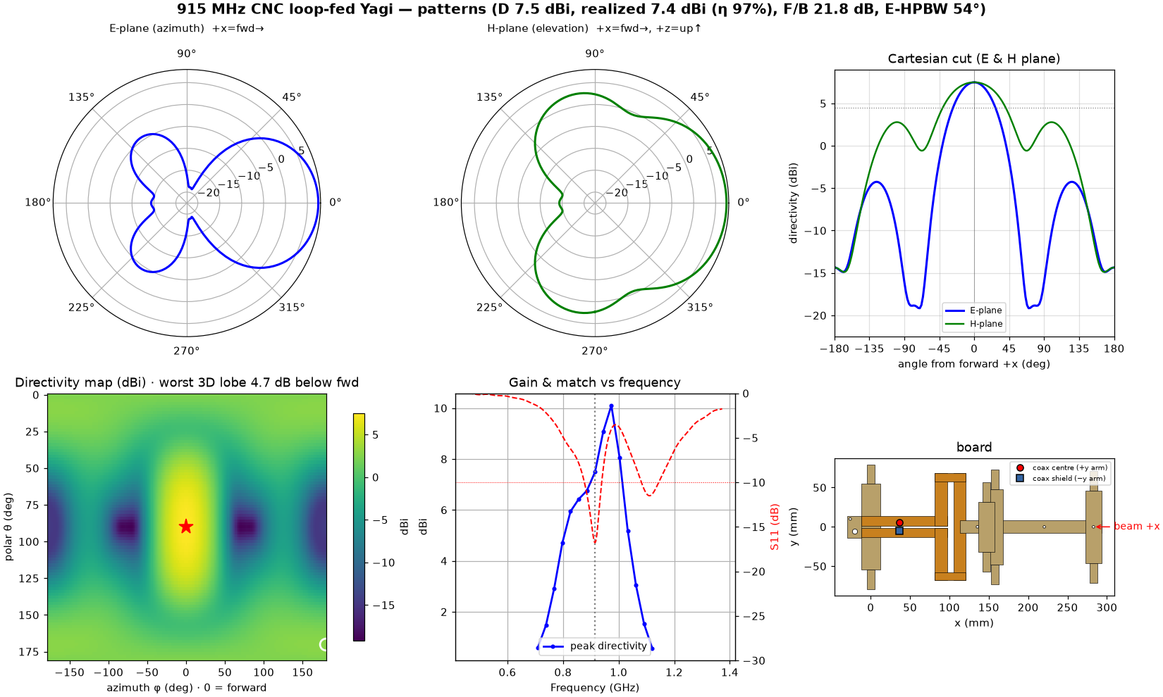
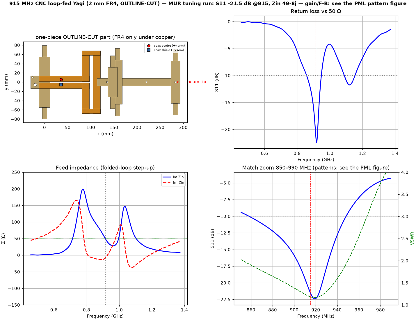
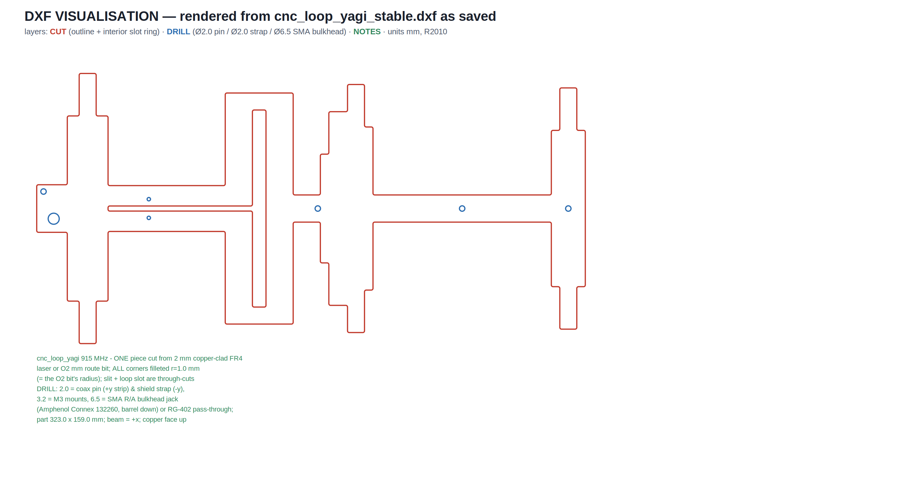
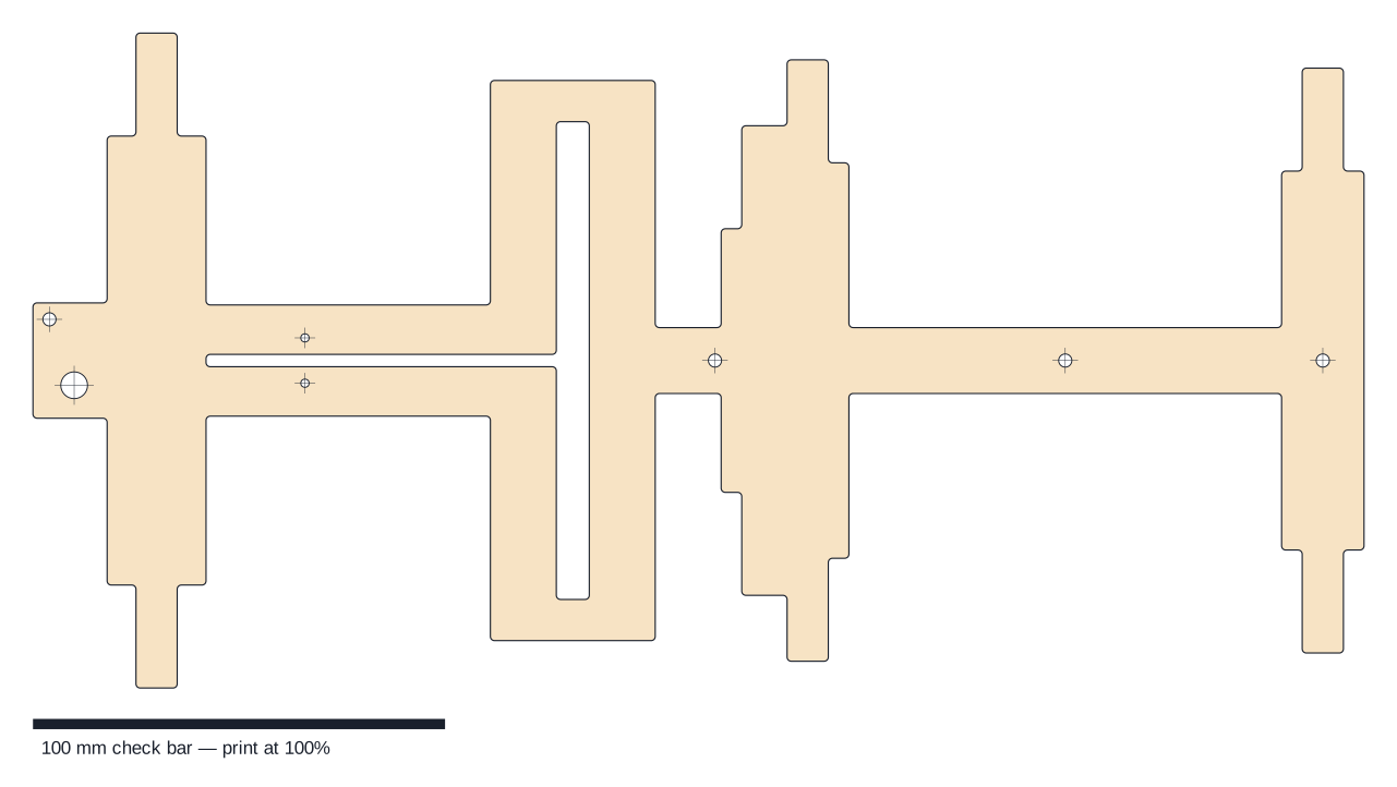
Both stabilities in one part — vs FREQUENCY (a hopping DF receiver sees the same antenna at every channel) and vs the LAMINATE (any stock FR4 bin). Geometry = the ROBUST tapered-FAT plus one extra strip: an OWA matching director (Breakall) — root 20 mm tapered to 10 mm tips like every parasitic, L 114, its leading edge 16 mm off the loop's front rail, boom-carried and bonded at its voltage null; tap re-tunes 43 → 45. WHY IT WORKS — impedance: with Q ≈ 11 a single-tuned match CANNOT hold VSWR ≤ 1.3 over 40 MHz (Fano bound); the close-coupled D0 adds the second pole (the classic OWA direct-50 Ω mechanism) and the Zin locus stops transiting 50 Ω and CURLS around it — and because the D0 is tip-tapered, the second pole rides the laminate exactly like the first. Pattern: the D0 re-shapes the array response so the F/B dome sits on the band instead of a point. MEASURED, PML_8 @ eps 4.45, one run, NF2FF at 895/905/915/925/935: F/B 17.3 / 20.6 / 21.8 / 18.5 / 14.7 dB — ISM-band spread 3.3 dB (ROBUST: 14.4, legacy FAT worse) · worst in-window F/B 14.7 still above the gerber quasi-Yagi's 915 headline (9.1) · D 7.49 dBi at 915, in-band spread 0.8 dB (η 97.2%; the ~1.1 dB vs ROBUST is the flatness price) · E-HPBW 58/58/54/54/50° · VSWR at the PML plane 1.55/1.40/1.34/1.43/1.69, ≤ 1.45 inside the ISM band (ROBUST hit 2.08 at the 935 corner). LAMINATE ENVELOPE (MUR, eps 4.2/4.4/4.6/4.8): VSWR@915 = 1.22/1.18/1.18/1.18 — worst 1.22 · res drift 3.4 MHz · BW₁₀ 90–92 MHz (the double-tuning dividend; ROBUST 79) · D and F/B constant to 0.04/0.1 dB · even the band-edge F/B triplet is eps-invariant (spread ≤ 0.5 dB): the frequency-stability is itself laminate-proof. Tuning history on the card charts: director stretch measured WRONG (top-edge F/B worsens), wide/untapered reflector measured WRONG (match degrades at 40 mm width, breaks at 60) — the OWA director is what works. Part 323×159 mm, one piece, same cut rules (Ø2 bit, r=1, drills Ø≥2), Ø6.5 rear-tab hole for the 132260 SMA bulkhead, single tap pair at 45. No rail/pair composition yet — unverified with the D0. Downloads: DXF + STEP + 1:1 + MUR & PML result JSONs.
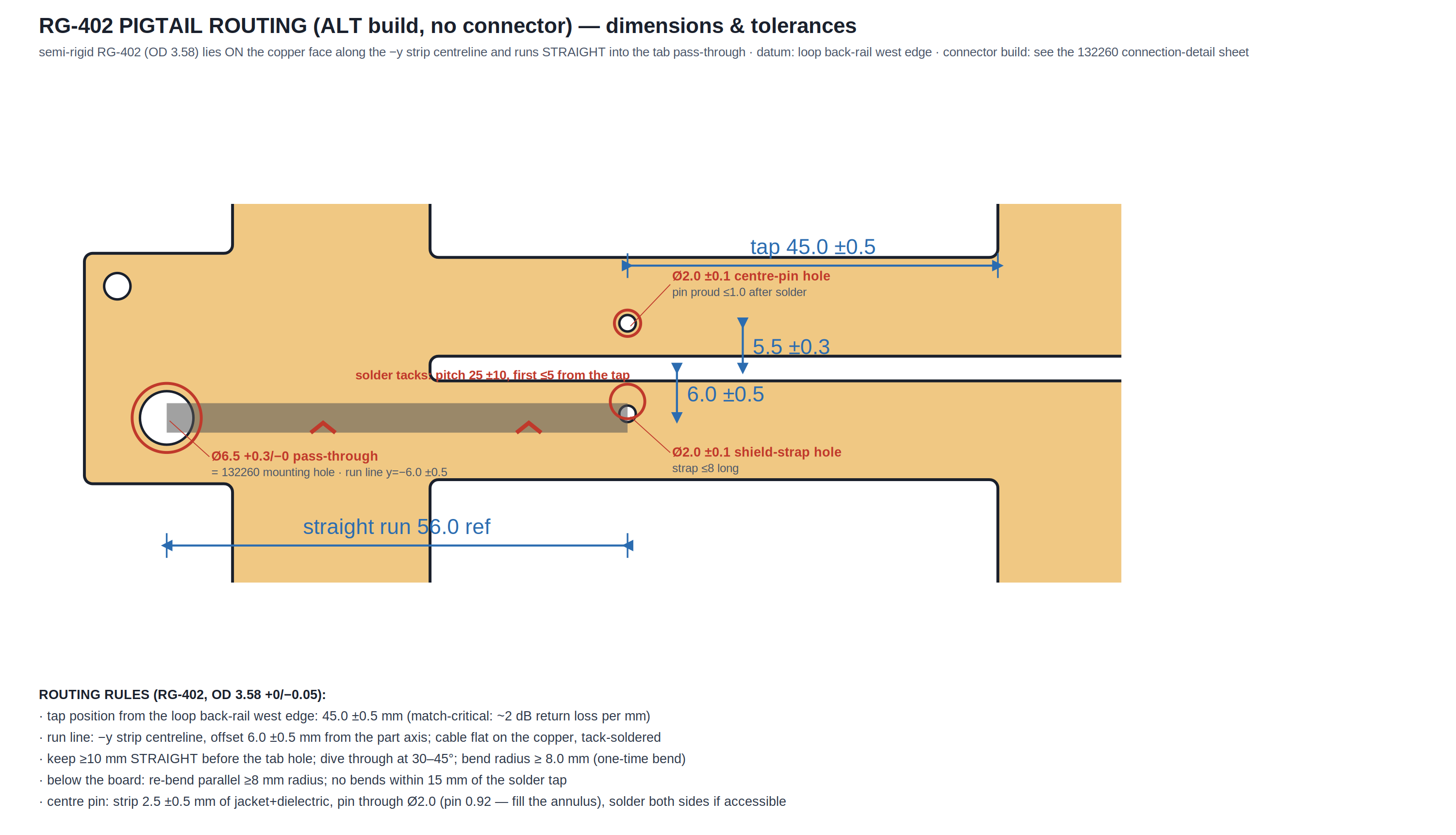
⬗ stack-up: copper-clad FR4 2.0 mm · ROBUST tapered-FAT base + OWA matching director (D0 114, gap 16, boom-carried) · tap 45 single pair · part CUT to the copper outline (laser or Ø2 mm route bit, corners r=1) · FR4 only under copper · feed: Amphenol Connex 132260 SMA R/A bulkhead + RG-400 jumper (or bare RG-402 pigtail)
Why a fifth element — the stability post-mortem, condensed
The ROBUST variant fixed the laminate problem but stayed frequency-dispersive: across 895–935 its F/B ran 30 → 12 dB (the resonant array's tuning curve) and its single-tuned match could not hold the band (Fano: Q ≈ 11 needs ≤ 6 for VSWR 1.3 over 40 MHz). Every cheap fix measured wrong: stretching directors made the top edge WORSE, widening or untapering the reflector degraded the match (60 mm breaks it entirely). What works is the OWA move — the matching director close in front of the driver, the same mechanism that lets amateur OWA Yagis feed 50 Ω coax directly with flat SWR across a band. Here it does double duty: its second impedance pole flattens the match (the Smith locus curls and dwells at 50 Ω — compare the CST-style flags), and its coupling re-shapes the array so the F/B dome covers the band (ISM spread 3.3 dB). Because the new strip wears the same 10 mm tip taper as every other parasitic, both poles move together with the laminate: VSWR@915 stays 1.18–1.22 and even the band-edge F/B triplet is eps-invariant over 4.2–4.8. One part, cut from any board in the bin, same antenna at every hop channel.
Balun common-mode diagnostic — the 22 mm stub, measured and closed
The slit balun's short sits at the reflector face, ~22 mm (λ/16) behind the tap — flagged for a long time as a defect since a proper slot balun wants λ/4. Measured with the house explicit-coax method (square coax hanging at the tap = deliberately WORST-case exit; I_cm/I_diff probes): as-built −16.5 dB common-mode suppression at 915 (−13.4 worst in-band). Every candidate fix was then measured: a λ/4 rear slot through the reflector centreline (quasi-Yagi truncated-ground style, web swept 40–73 mm — the rear slot's eps_eff ≈ 2.3 was itself measured from the 73 mm web's 544 MHz notch) buys only ~1.5 dB and its notch pins at structure modes (820/546 MHz), not at the stub length; even deleting the short entirely (unbuildable — it is the one-piece connection) reaches just −21.5. Verdict: the slot short is NOT the CM-controlling element of this plate; the defect is real but bounded and no board-level redesign is worth its cost. The shipped build already uses the gentle exit (132260 behind the reflector, in the parasitic shadow — the pigtail A/Bs measured the match cable-independent there); if a bench build ever shows cable-position sensitivity, a clip-on ferrite at the connector outperforms every board option measured. Diagnostic module: cnc_loop_cm.py (3-case compare + web walk).