Resolution vs spacing — click a full-wave anchor for its diagrams & fits (no sweeps)
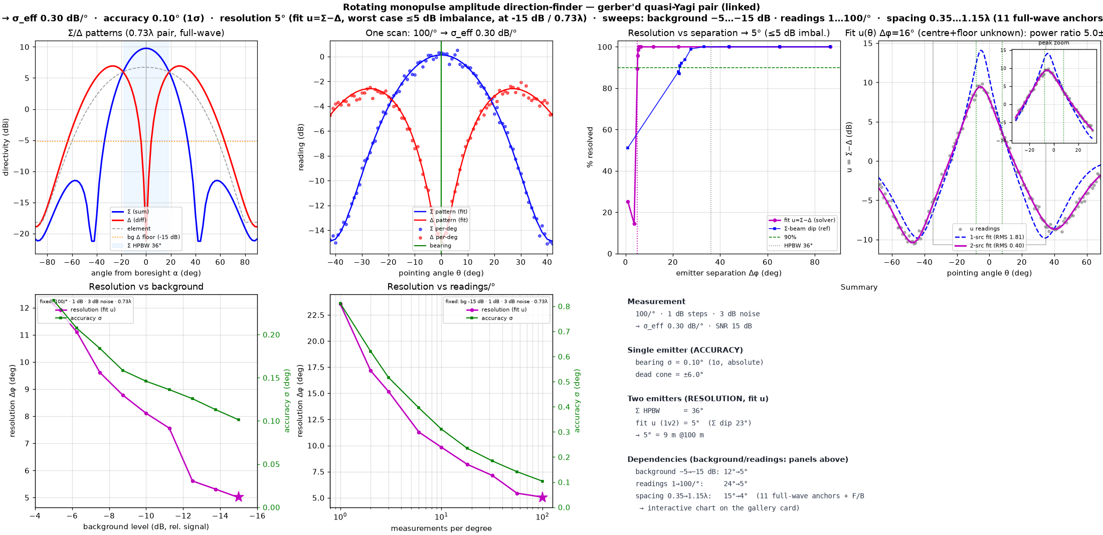
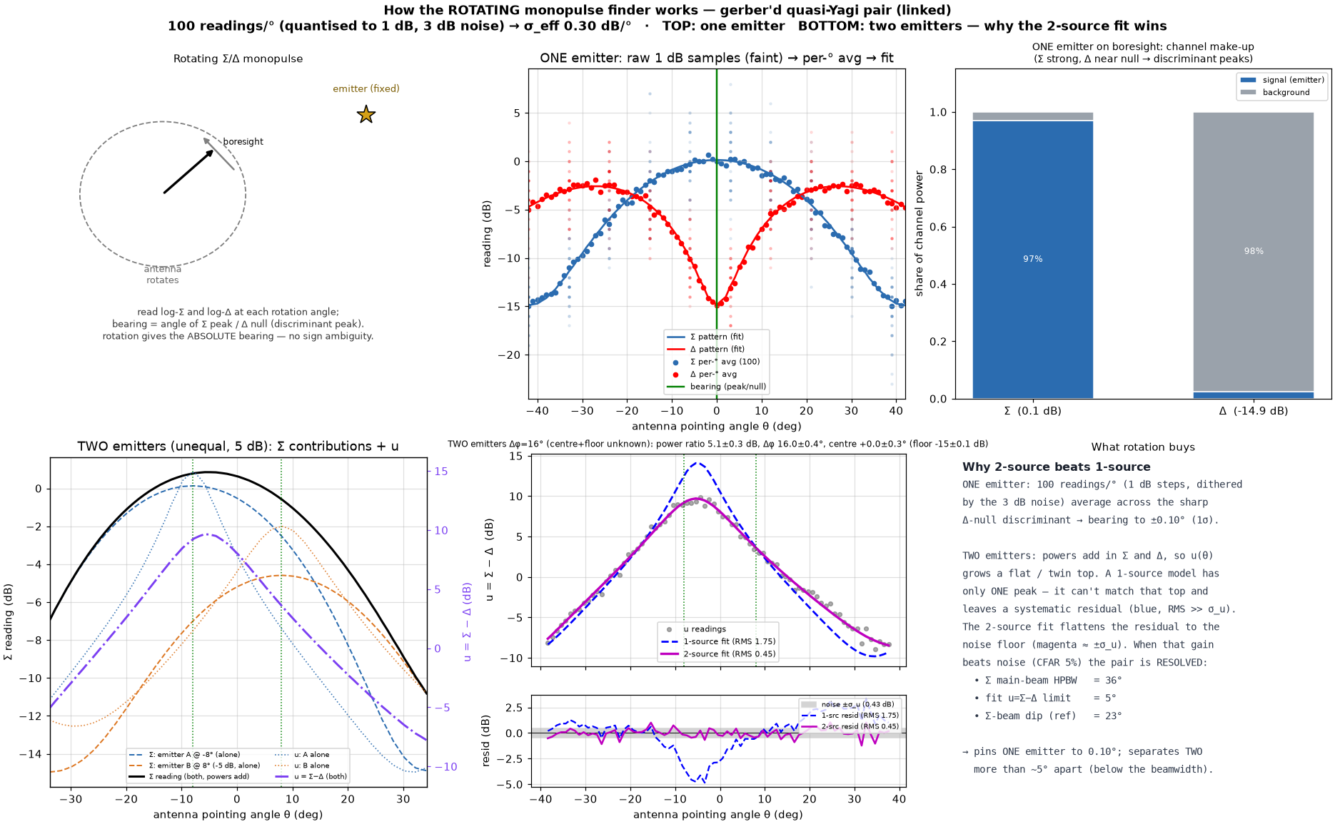
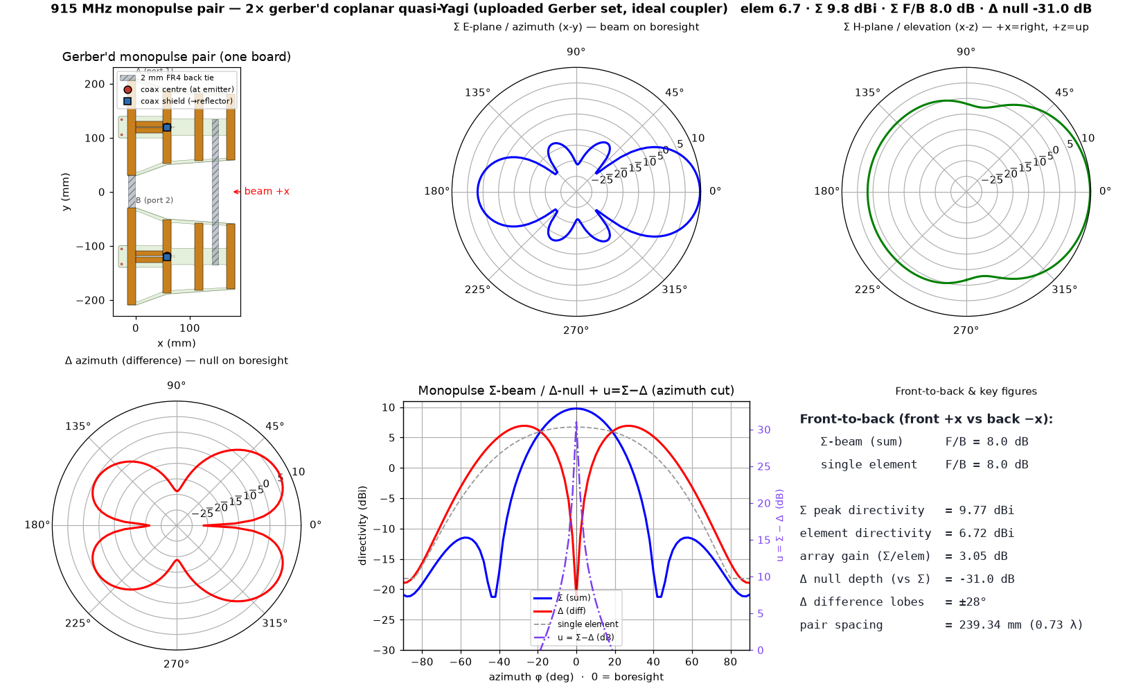
ROTATING monopulse (log Σ/Δ amplitudes, no phase) → absolute bearing, no sign ambiguity · full-wave Σ/Δ pair of the ACTUAL gerber'd element (gerber_yagi, digitised from the uploaded Gerber set; single-element re-check 8.9 dBi / 902 MHz / S11 −24 dB @915), mechanically joined by TWO identical 12 mm-wide × 2 mm FR4 backing splice strips placed ONLY on the voltage-null lines (matching the coplanar_monopulse_linked convention): REAR across the reflectors and FRONT across the boom spine BETWEEN dir-1 and dir-2 — longitudinal field minima, off every element tip and the feed slot. Each tie is now LENGTHENED in y to fully CROSS each board's ~22 mm copper boom (overrunning it by 4 mm), so the two boards can be screwed + bonded into one rigid pair with real overlap — re-simulated at the 0.60λ design point this is RF-negligible (ΔΣ F/B 0.03 dB, Δ null 0.06 dB, gain unchanged), since the ties still ride the longitudinal field-null spine; they still deepen the Δ null to ≈−28…−34 dB (vs −21…−25 dB unlinked) · measurement: 100 readings/°, 1 dB detector steps, 3 dB noise (dither) → σ_eff 0.30 dB per 1° reading · single-emitter ACCURACY 0.10° (1σ) · two-emitter RESOLUTION 5.0° for UNEQUAL emitters (WORST case, powers within 5 dB), by a 1-SOURCE GOODNESS-OF-FIT of u=Σ−Δ with the single-source null free in bearing (CFAR 5%) — ~7× below the 36° Σ beamwidth (≈8.8 m @ 100 m) · resolution depends on: background −5→−15 dB ≈ 12°→5° · readings 1→100/° ≈ 24°→5° (accuracy 0.8°→0.1°) · pair spacing 0.35→1.15λ ≈ 15°→4.5° — shape-preserving interpolation THROUGH 11 full-wave anchors (0.40λ 14.9° · 0.50λ 5.3° · 0.52λ 5.4° · 0.54λ 5.2° · 0.56λ 5.1° · 0.58λ 5.2° · 0.60λ 5.2° · 0.73λ 5.0° · 0.85λ 4.7° · 1.0λ 4.6° · 1.15λ 4.5°) · REFINED 0.50–0.60λ band for max Σ front/back: F/B rises 7.5→8.6 dB across the band and PEAKS at 8.6 dB @ 0.60λ (196.7 mm) — the best-F/B spacing between the reflector-merge floor below ≈0.50λ and the nominal 0.73λ (F/B then falls to 8.0 dB by 0.73λ) · 0.40λ is far coarsest (the 179 mm reflectors merge → near-bidirectional, Σ F/B −0.8 dB), >1λ shaded (grating lobes → ambiguous bearing) · the SAME u=Σ−Δ scan reads out an UNEQUAL pair's power ratio via a continuous 2-source fit with pair CENTRE free + noise floor from the ROTATION MINIMUM (neither assumed known): at a resolved 16° split, ratio 5.0±0.3 dB, centre ±0.3°, floor ±0.1 dB
⬗ stack-up: FR4 1.6 mm (εr 4.3) · 1 oz Cu (35 µm) · single layer, routed flared frame 215.5×179.3 mm per element · 2× 2 mm FR4 back-tie splice strips (reflector + dir1/dir2 field nulls) · 2-element Σ/Δ @ 240 mm (0.73λ); best F/B @ 0.60λ