Statistical resolution limit (SRL) — closest two targets tellable apart vs SNR · hover a point (session 014z DF model)
The part
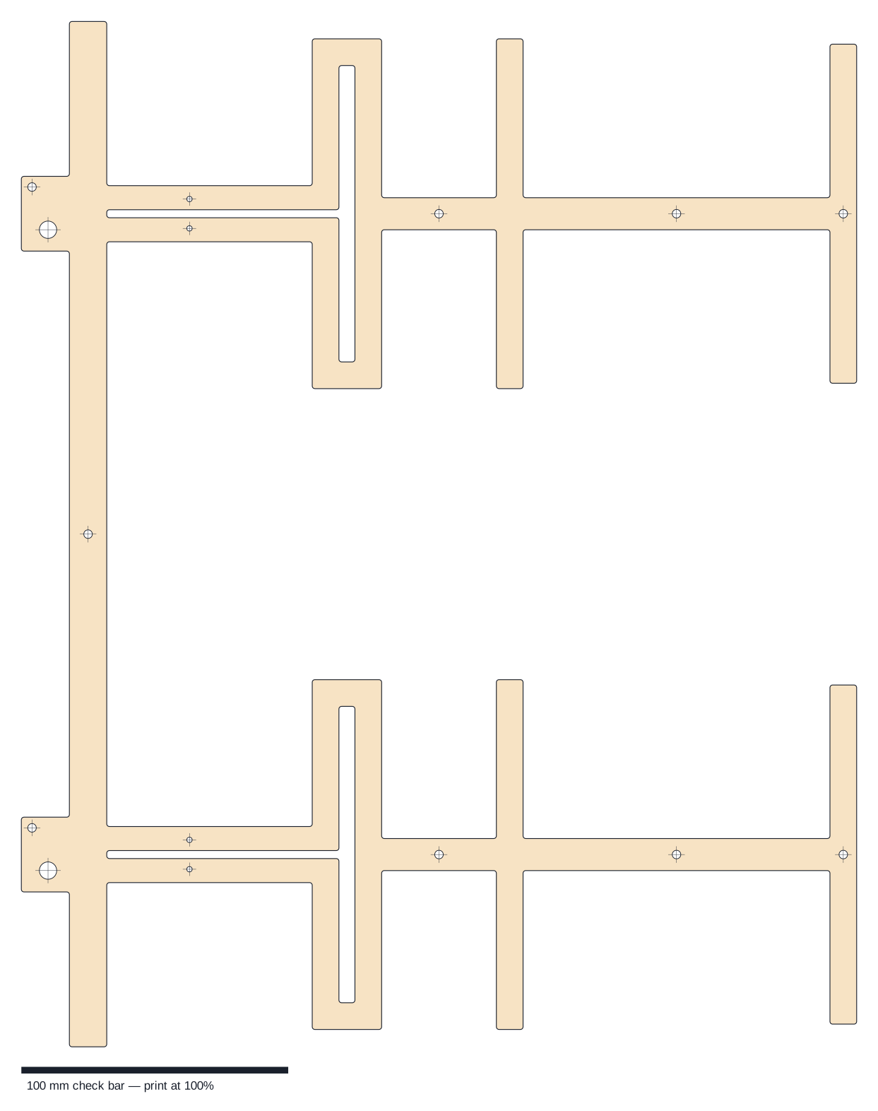
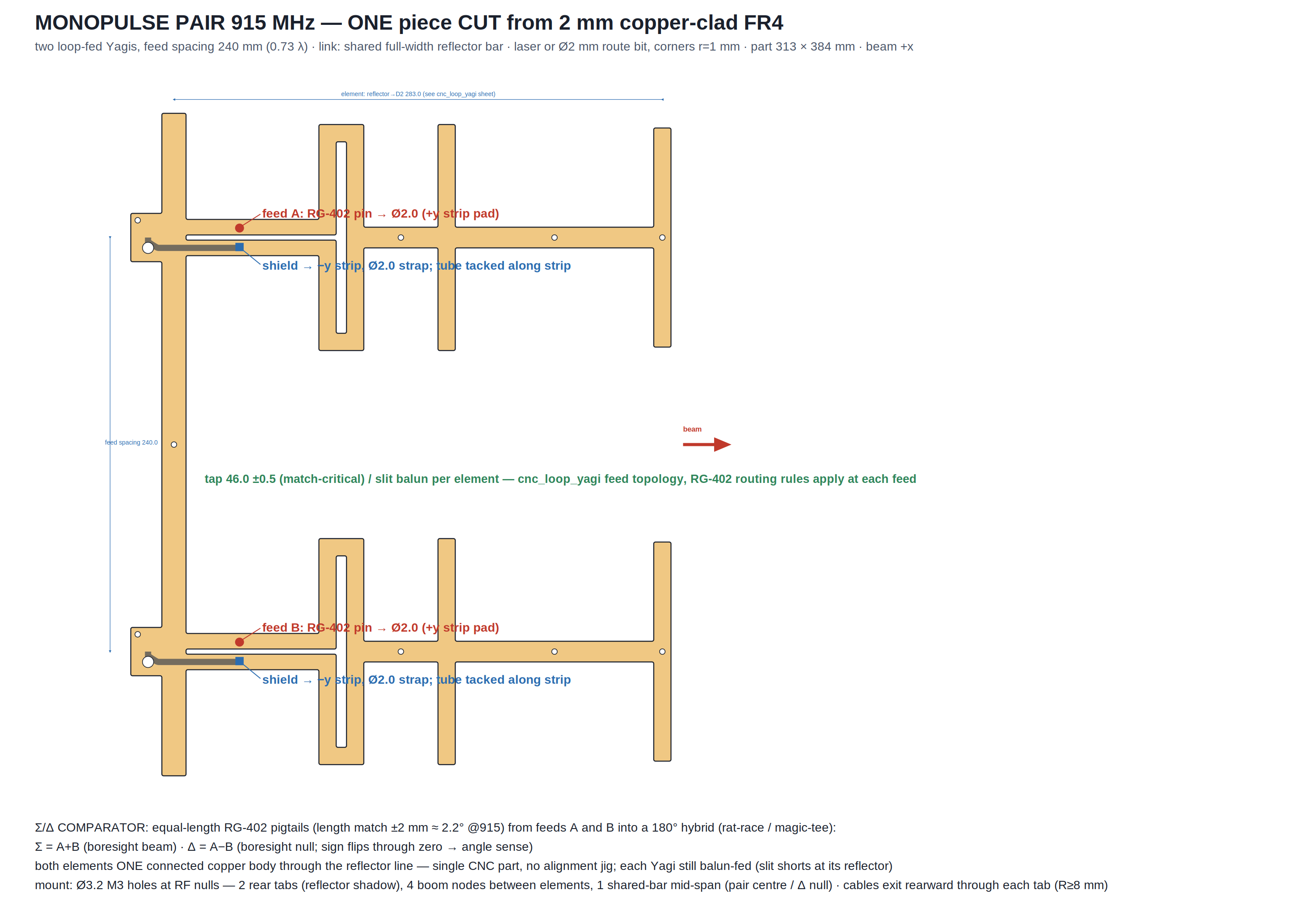
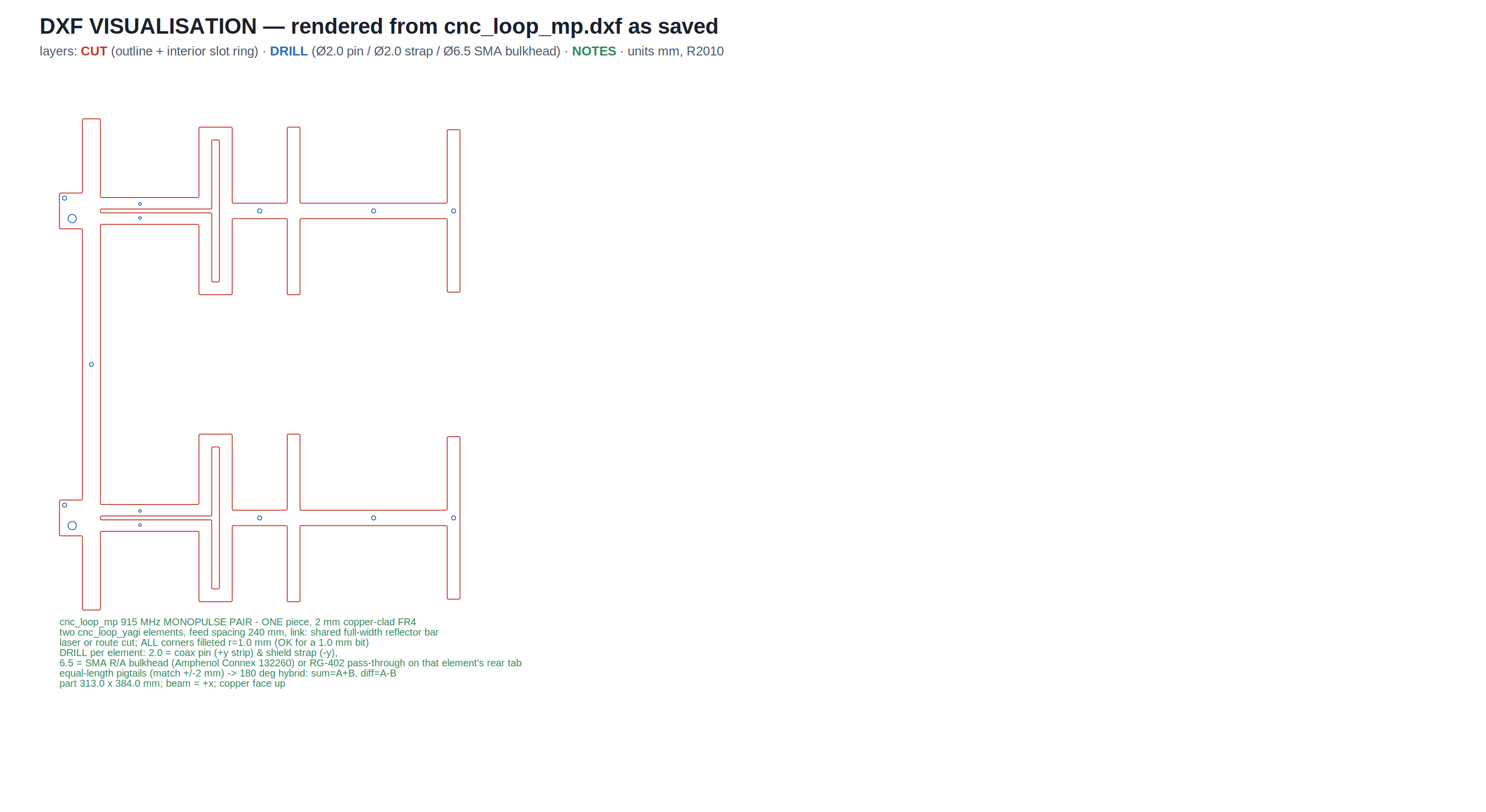
Two 4-element loop-fed Yagis cut as a single piece of 2 mm copper-clad FR4, joined through a continuous full-width reflector bar — one CNC path, no alignment jig, and the pair-level tolerances (spacing, parallelism, coplanarity) collapse to router precision. Each element keeps the full single-Yagi feed: the slit between the CPS strips shorts at the reflector (λ/4 slot balun at 915 MHz), the coax taps the slit 50 mm behind the loop (the air-slot section transforms the loop impedance down to 50 Ω), and an RG-402 pigtail solders pin-to-strip and shield-to-strip, then exits through its own rear tab. The elements are deliberately wide (20 mm directors, 16 mm loop rails, 24 mm reflector, 16 mm boom): a wide strip is a thick dipole — flatter reactance slope, lower Q, wider match (element BW₁₀ 69 vs 52 MHz thin) — and the frame is rigid enough to carry itself. The second pair of tap drills 4 mm forward is εr insurance: FR4 batches at the hot end (εr ≥ ~4.45 at UHF) cross a feed mode boundary that breaks the tap-50 match; resoldering the pigtail at the 46 mm holes restores a serviceable match. The Δ null never cares — it is symmetric and εr-immune (62–64 dB at every εr probed).
Σ and Δ — the honest finals (PML_8, 120 mm air box)
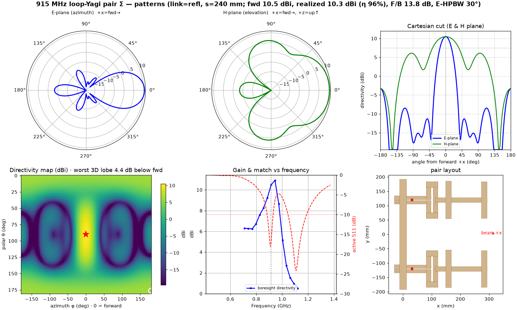
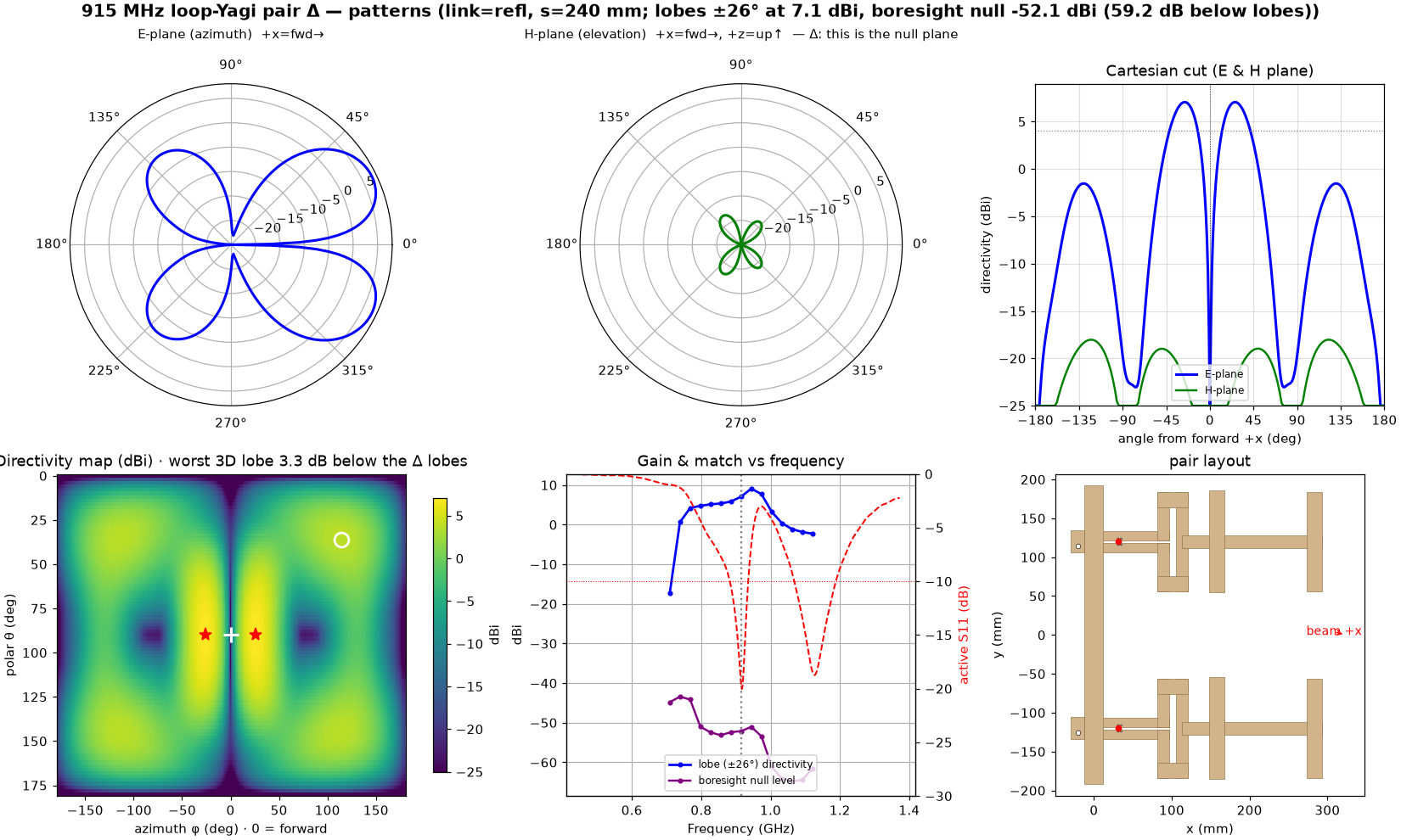
Each mode is its own full-wave run with the two ports driven (1,1) or (1,−1), so mutual coupling is inside the solve — and each is shown on the same six-panel kit every card carries: E- and H-plane polars, the Cartesian cut, the full-sphere directivity map (worst 3D lobe circled in white), gain and active match vs frequency, and the layout. MUR boundaries are used for the relative A/B tables further down; every absolute number in this card's header comes from these PML_8 finals. Σ: 10.5 dBi forward, η 96%, −16.8 dB active match, E-HPBW 30°; in the azimuth plane the biggest lobe outside the main beam is the 180° rear at 13.8 dB (every lateral sidelobe sits lower), and over the full sphere the worst lobe is the polar rear-elevation pair only 4.4 dB below forward — the elevation lobes every single-plane planar Yagi has. An azimuth DF scan never points there, but sky and ground interference does live there; a reflector plane under the array is the fix if that path ever matters. Δ: a −52 dBi boresight null 59.2 dB below the ±26° difference lobes, S11ₐ −19.6 — and the null is not a point but the whole x-z plane (the H-plane panel IS the null plane, so the elevation lobes never fill it). The null-vs-frequency trace on the gain panel shows it holding across the band (59.3 dB at both ISM edges): pattern bandwidth is not the limit, the comparator's balance is (a 0.2 dB / 2° hybrid imbalance caps the system null near 35 dB). Δ's worst 3D lobe sits 3.3 dB below the difference lobes at θ=36°/φ=114° — the elevated cousin of the ±130° azimuth sidelobe (8.6 dB in-plane).
The match — S11 and VSWR, both builds, both modes
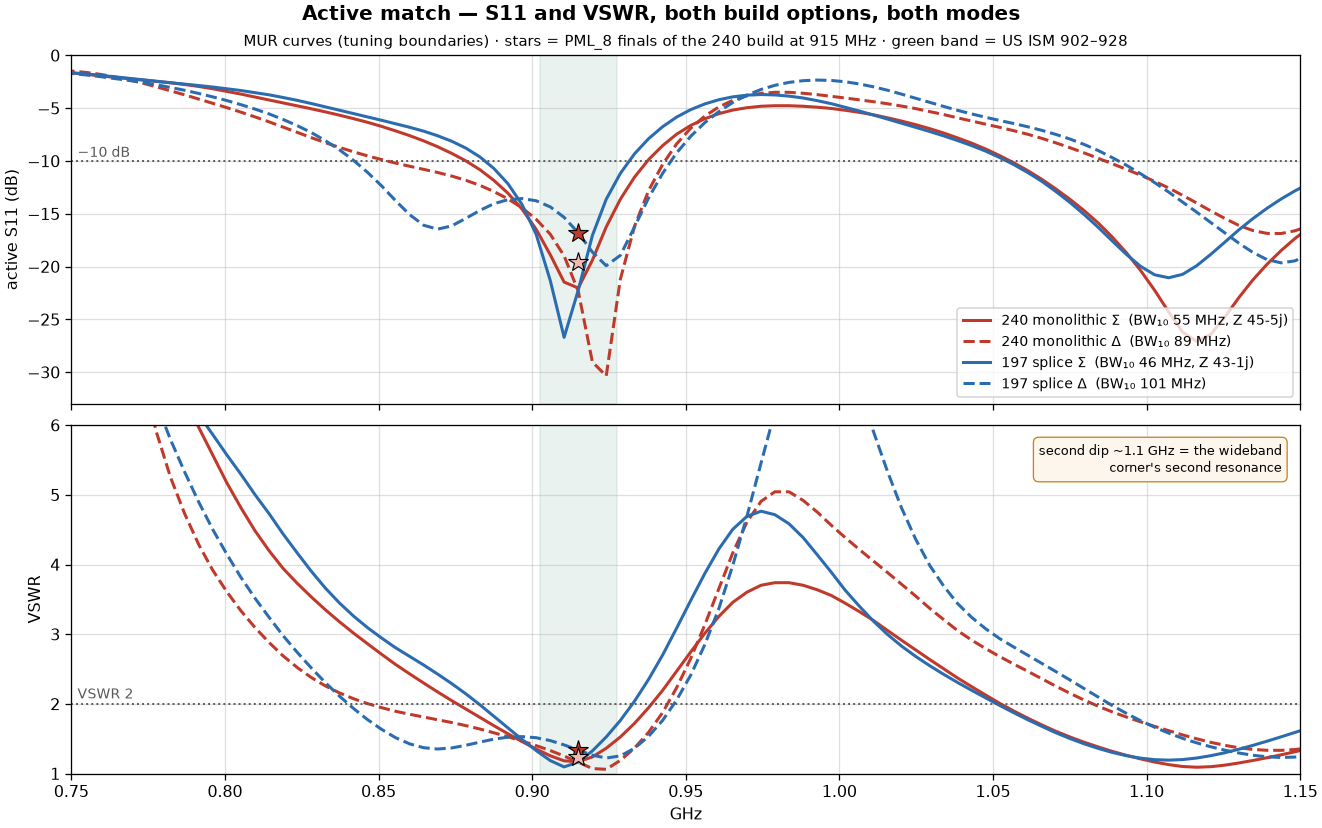
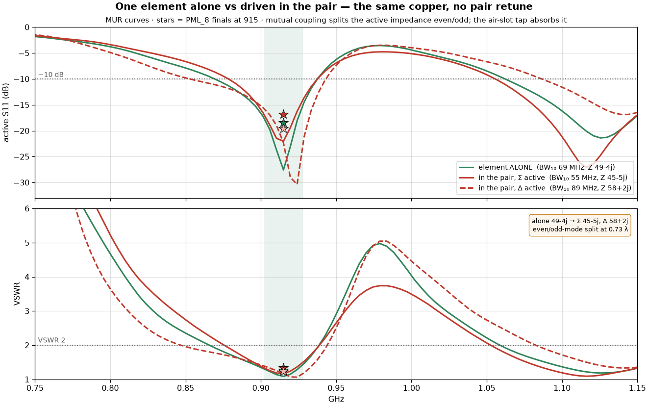
Active S11 — each element's reflection with both ports driven in the mode, so the mutual coupling a lone-element measurement misses is inside the number — for the two build options in both modes, VSWR below, US ISM band shaded. The curves are the MUR tuning runs (they nail shape and bandwidth); the stars at 915 mark the 240 build's PML_8 finals from the header (Σ −16.8, Δ −19.6 dB) — MUR flatters absolute depth, so read depth from the stars and width from the curves. The two modes see different impedances because even- and odd-mode coupling split the active Zin: Σ lands at 44.7−5.4j (240 monolithic) and 42.8−0.6j (197 splice) with 46–55 MHz of −10 dB width, Δ at 57.9+2.5j and 55.7+14.3j with roughly twice that (89–101 MHz) — the tap is tuned to center the narrower Σ mode, and Δ rides along with margin. Both builds, both modes stay under VSWR 2 across the whole 902–928 band. The second dip near 1.1 GHz is the fat elements' second resonance — the wideband corner the elements were widened for.
The element, and how it is tuned for the couple
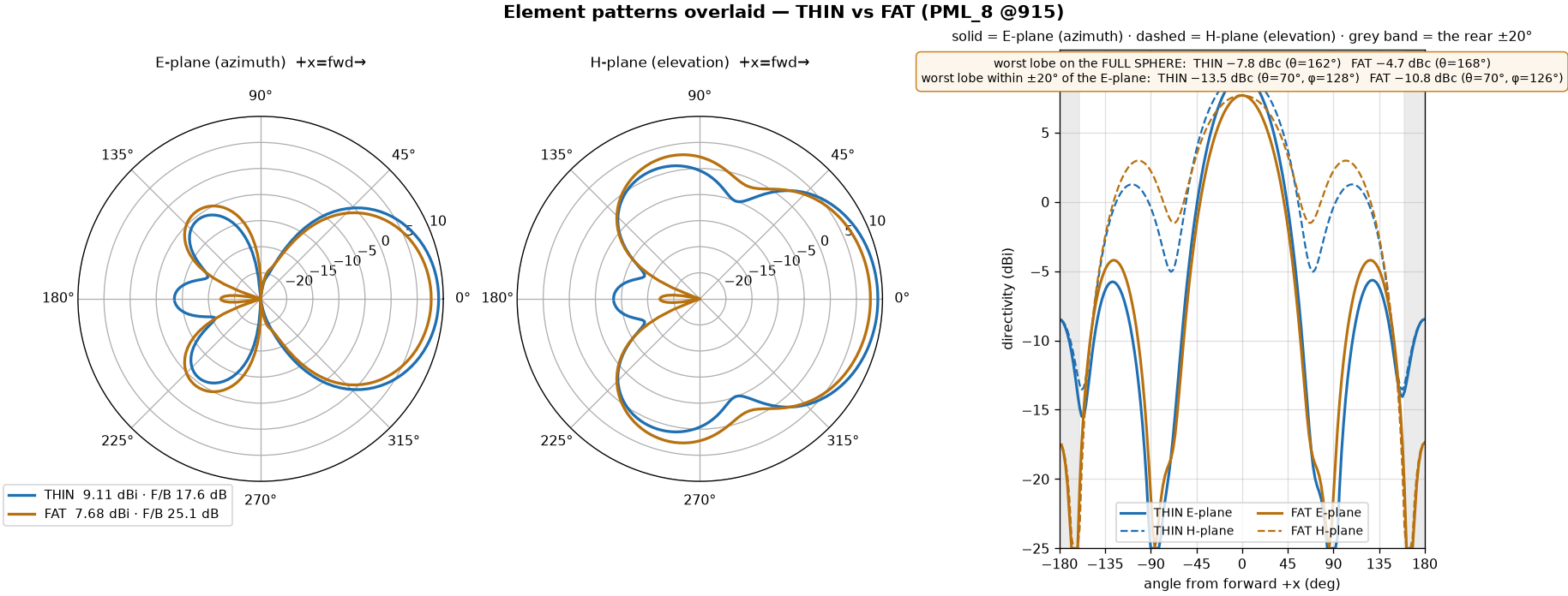
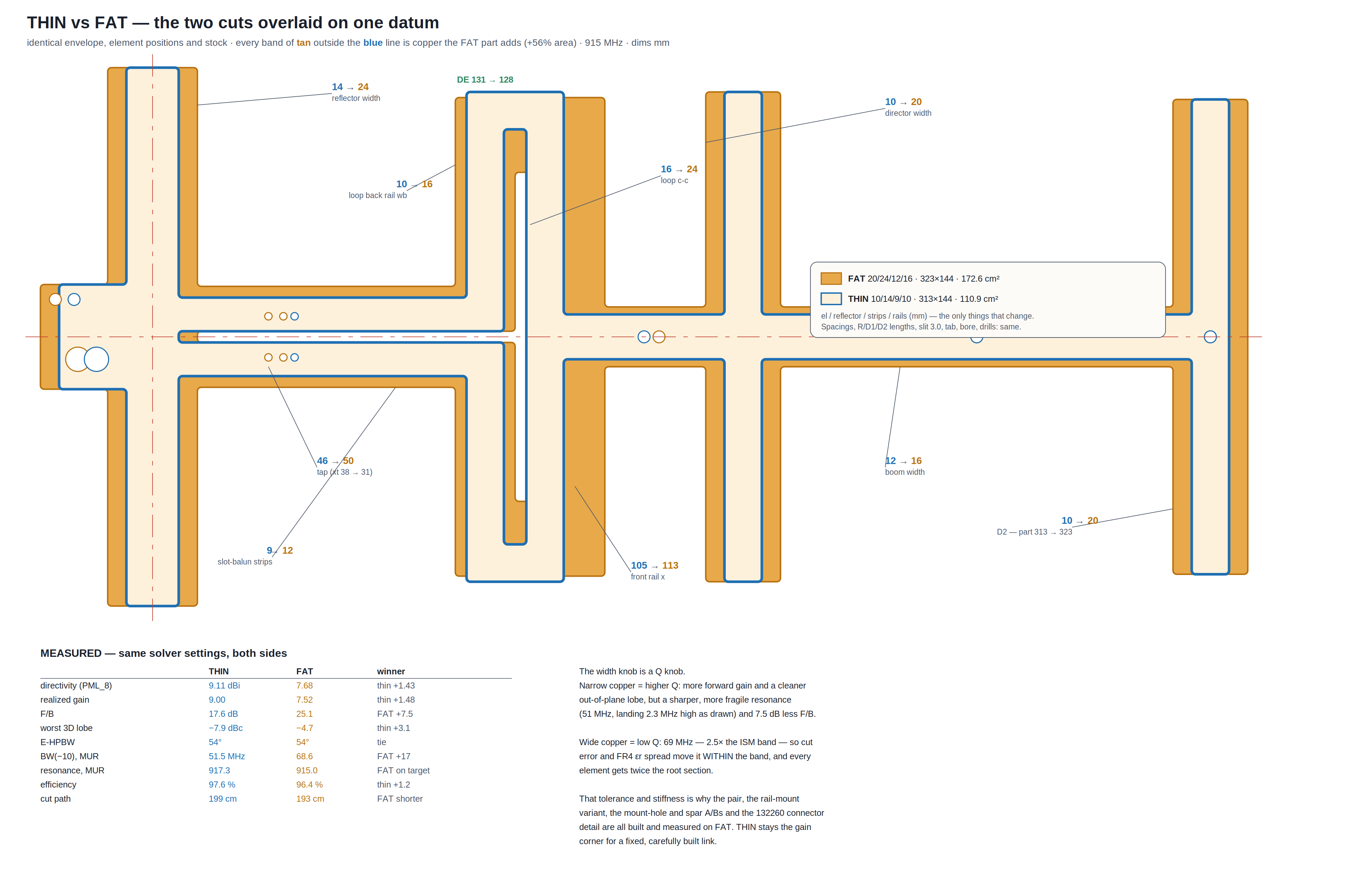
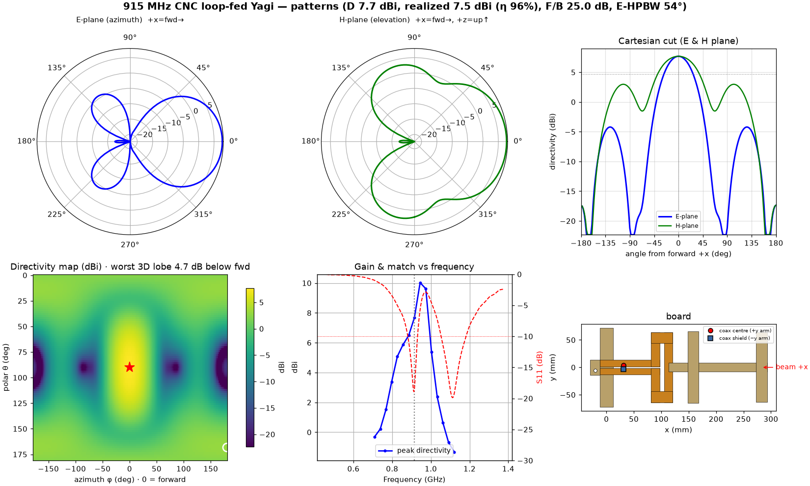
The pair is two of these — the wide-element loop-fed Yagi, on the same six-panel pattern kit every card carries (PML_8: 7.7 dBi directivity, η 96%, F/B 25.1 dB, E-HPBW 54°; fattening the elements traded ~1.4 dB of the thin element's directivity for +7 dB of F/B and a 69 MHz element match). The kit's directivity map also carries the forward-to-worst-3D-sidelobe number: 4.7 dB, a polar down-back lobe at θ=168° — the elevation lobes every single-plane planar Yagi has (the thin element does 7.9 dB; the wide H-plane is what the fat elements paid). In the azimuth plane — where the DF scan actually lives — the worst lobe is the 25 dB rear. Tuning for the couple is deliberately NOT a retune — the element is tuned alone to 915 (res 915.0, S11 −27.6, Zin 48.7−3.9j) and the pair reuses identical copper. What the couple changes is electrical: with both ports driven, mutual coupling splits each element's ACTIVE impedance by mode — even (Σ) sees 44.7−5.4j and keeps its dip at 915; odd (Δ) sees 57.9+2.5j, slides to 924 and widens (55 vs 89 MHz of −10 dB active bandwidth). The overlay shows all three curves nearly superimposed through the ISM band. The split is absorbed in two places: the air-slot tap transformer has match bandwidth to spare (the ±20% active-impedance excursion still leaves both modes at or below −16.8 dB at 915 in the PML finals), and the spacing was chosen with the split in mind — at 0.5λ the even-mode active match collapses to −12.6 dB, the classic coupled-pair impedance split; by 0.60λ it is safe, and at 0.73λ the excursion is small. The rule that fell out of the tuning: tune the element alone, then verify both ACTIVE matches in the pair — when the Σ and Δ dips straddle the target (915 and 924 here), leave the geometry alone. A mode split cannot be trimmed away by length (trims move both dips together); it can only be absorbed by match bandwidth.
Can two Yagis be one part? — the link study
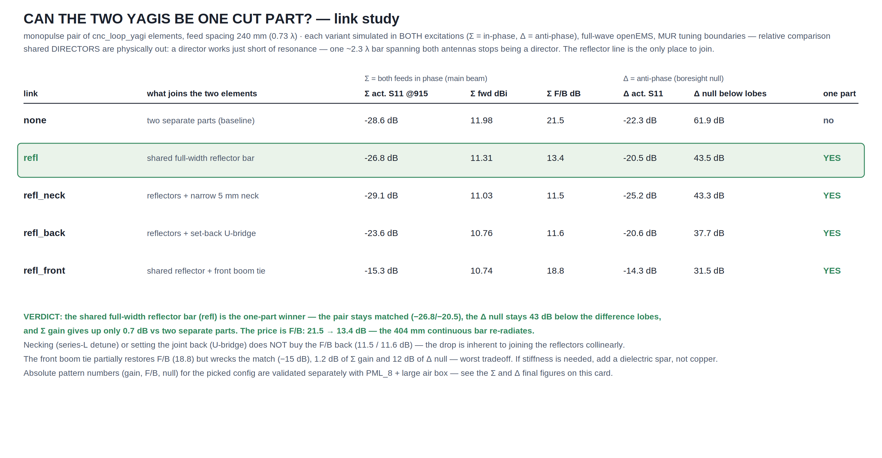
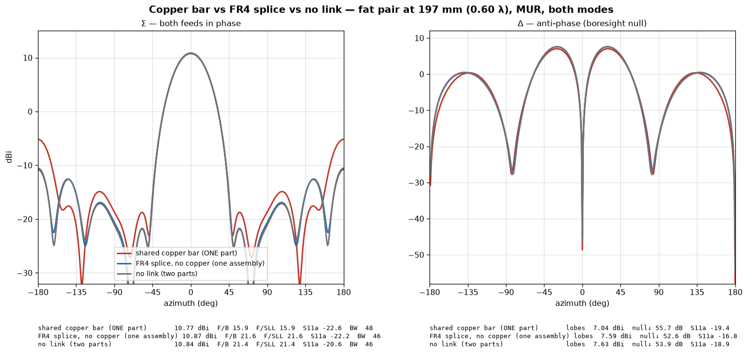
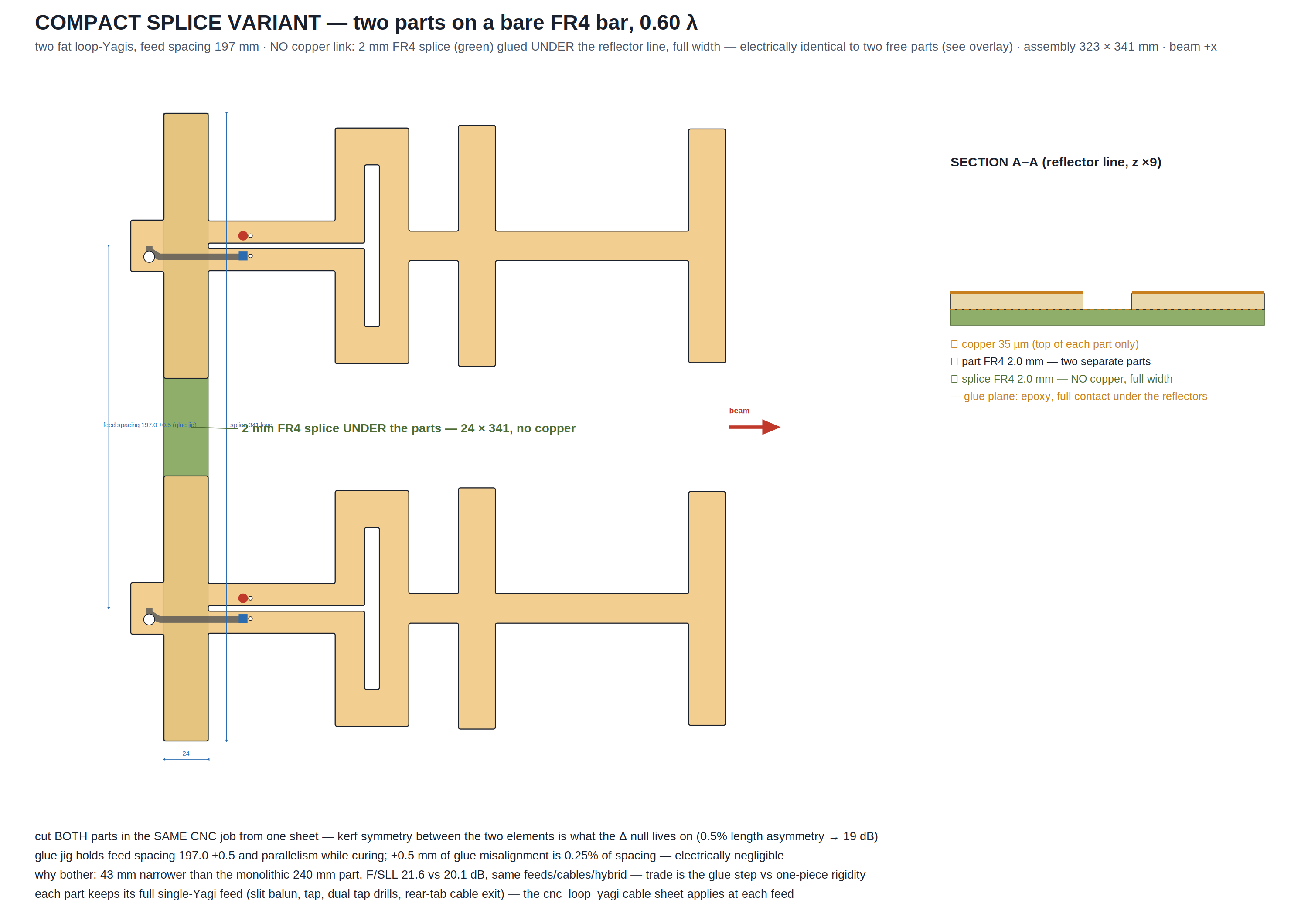
Every way of joining the two elements, simulated in both modes (thin-element study, MUR, relative). The shared full-width reflector bar is the only join that keeps the pair matched and the null deep. Narrowing the joint or setting it back does not recover the F/B it costs; a copper tie between the booms partially does, but wrecks the match, a dB of gain and 12 dB of null. Shared directors are ruled out by physics: a director works just short of resonance, and one bar spanning both antennas is ~2.3λ long. If extra stiffness is ever needed, add dielectric, not copper. Measured coda at 0.6λ: a copper-free 2 mm FR4 splice bar glued UNDER the reflector line (full pair width) is electrically indistinguishable from no link at all — F/B 21.6 vs 21.4 dB, every curve superimposed in both modes — while the copper bar at the same spacing gives up 5.7 dB of F/B and F/SLL. So the dielectric spar is confirmed free: if a compact 0.60λ footprint matters more than monolithic construction, cut the two parts in the same CNC job and splice them on the bare FR4 bar (323×341 mm assembly, F/SLL 21.6) instead of sharing copper. The assembly drawing below shows that build: the 24×341 mm bare splice bar glued under the reflector line, the glue-jig dimension (feed spacing 197.0 ±0.5 mm — ±0.5 mm is 0.25% of spacing, electrically negligible), a section through the copper/FR4/glue/splice stack, and both feeds unchanged from the single element.
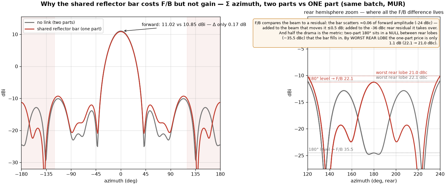
Why the bar costs F/B but not gain
Same batch, same boundaries, the only difference is the bar (Σ mode, wide elements). Forward, the beam is the coherent sum of both Yagi apertures: the bar scatters at roughly −24 dB relative to it, and adding a −24 dB field to the main beam moves it by at most half a dB — measured 0.17 dB. Behind, the pair has already cancelled itself to a small residual, so the same scattering dominates: F/B is a ratio of a big number to a tiny one, and perturbations invisible against the numerator take over the denominator. The other half of the drama is the metric itself: the two-part pair's φ=180° point happens to sit in a null BETWEEN rear lobes (−35.5 dBc) which the bar's re-radiation fills in. Judged by the worst rear lobe — the number that actually sets DF back-ambiguity — the one-part price is only 1.1 dB (22.1 → 21.0 dBc), and by forward-to-biggest-sidelobe it is 1.0 dB (21.1 → 20.1 dB, the ±114° lobe in both cases).
Spacing, tolerance, noise — the full study
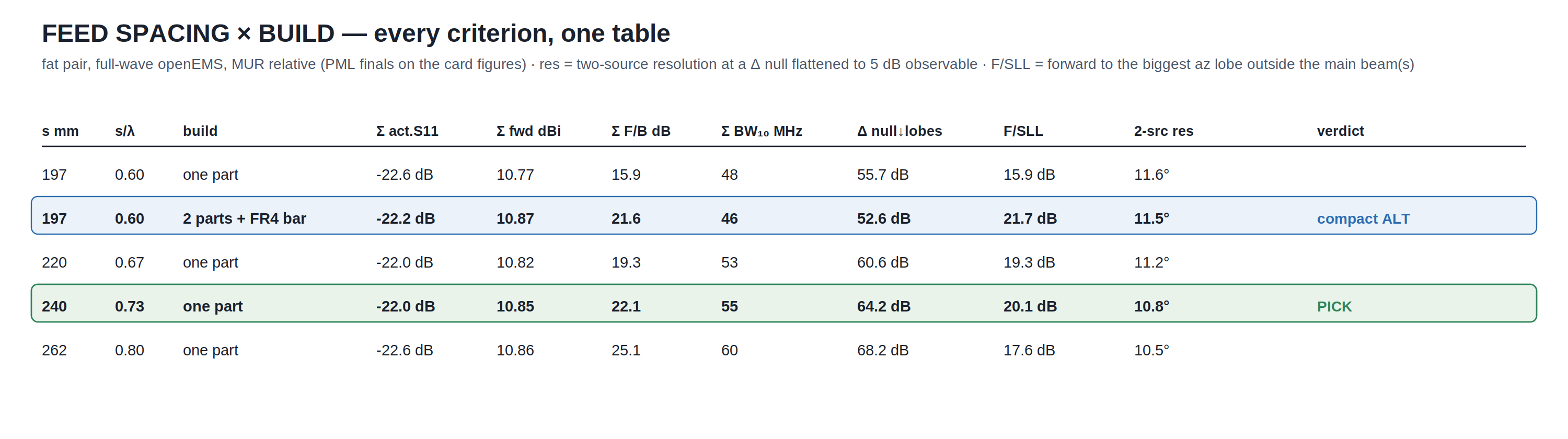
Feed spacing swept 0.5–0.8λ with every criterion in one table: 0.5λ is disqualified outright (the even-mode active match collapses to −12.6 dB — the classic coupled-pair impedance split), while F/B, Δ null and Σ bandwidth all rise with spacing, and the two-source resolution under heavy noise (Δ null flattened to 5 dB observable) is spacing-flat at ~11°, still 2.2× better than scanning the Σ beam alone. 240 mm keeps the seat among the one-part builds: forward-to-biggest-sidelobe — the largest azimuth lobe anywhere outside the main beam, rear or side — peaks exactly there (15.9/19.3/20.1/17.6 dB across the sweep: below 240 the rear lobe dominates, above it the ±114° sidelobe takes over). The second 0.60λ row is the two-parts-on-an-FR4-bar splice build from the link study: it actually tops the F/SLL column (21.7 dB — its biggest non-main lobe IS the rear lobe, nothing lateral is worse) and matches the one-part builds everywhere else, giving up only Δ-null depth (52.6 vs 64.2 dB, both far beyond any comparator's balance) and 9 MHz of Σ bandwidth — the compact choice when 43 mm of width matters more than monolithic construction. Production tolerance: kerf drift between the two elements is the one null killer (0.5% length asymmetry → 19 dB; real routers hold 0.05–0.1% between elements of one part → ≥40 dB) — the one-part cut minimizes exactly this class, and the splice build keeps it too (both parts cut in the same CNC job; the glue jig holds spacing to ±0.5 mm, 0.25% of spacing, electrically negligible). εr never touches the null (62–64 dB at every εr probed) and the match is safe through εr 4.0–4.4; past the ~4.45 mode crossing the tap-50 match breaks (−7 dB ≈ 0.9 dB mismatch loss) — resolder the pigtail to the 46 mm drill pair if the built antenna reads SWR > 2.5. Cable phase: ±2 mm between the two RG-402 pigtails ≈ 2.2° at 915 ≈ ~0.5° boresight bias at 0.73λ — cut both from one stick. Calibration against the gerber'd-finder cards, whose headline reads 5.0°: those numbers sit at a −15 dB background, not this table's flattened-to-5-dB null (≈ −6 dB background). Re-run at a matched background with the same Monte-Carlo machinery, this pair resolves 5.3–5.5° at −14 dB and 4.3–4.5° at −18 dB — the difference between the cards' quoted numbers is the noise operating point, not the antennas.
Feeding Σ and Δ
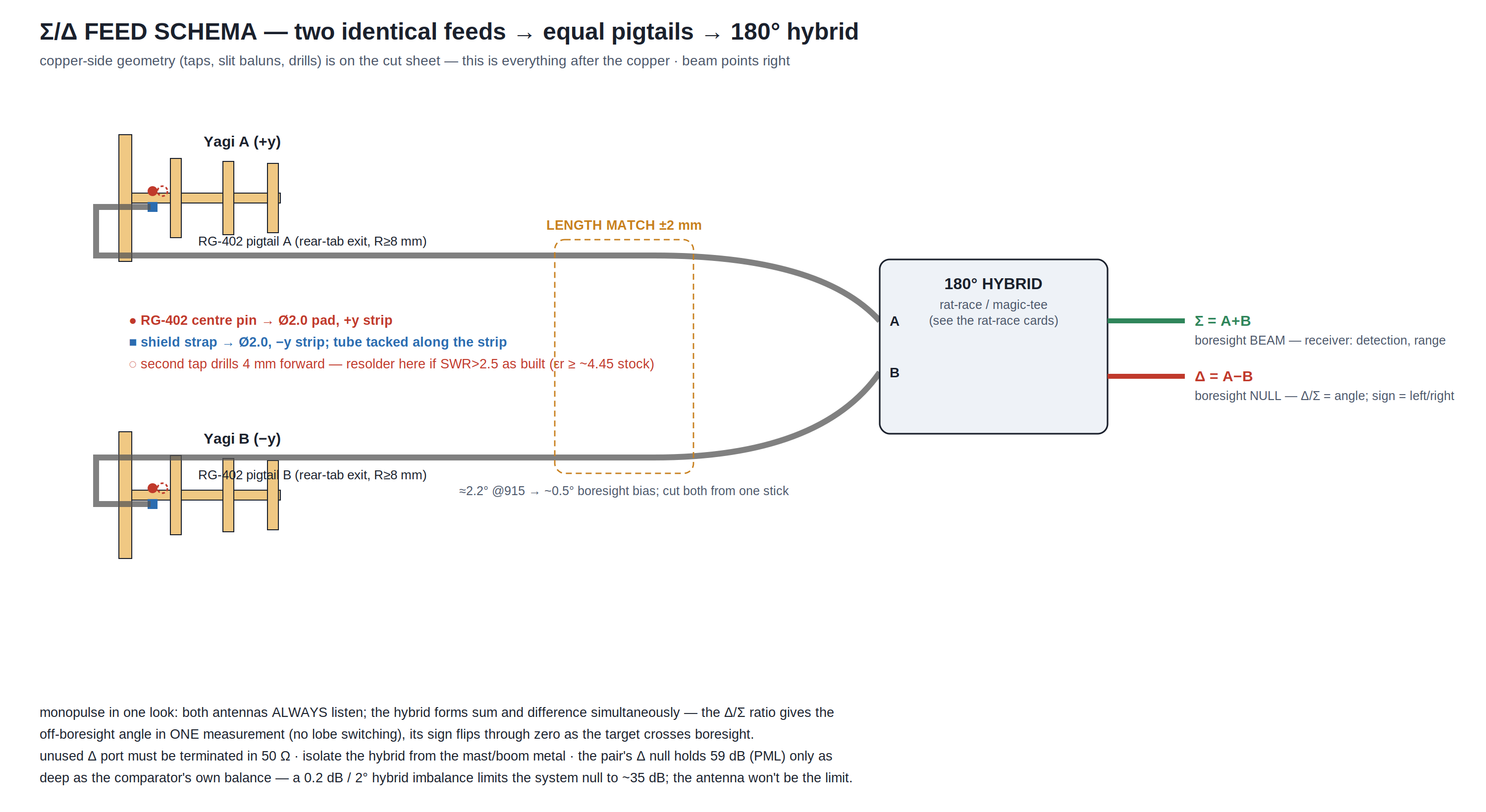
Everything after the copper: two equal-length RG-402 pigtails (±2 mm ≈ 2.2° at 915 — cut both from one stick) into a 180° hybrid, rat-race or magic-tee. The hybrid forms sum and difference simultaneously: Δ/Σ is the off-boresight angle from a single measurement and its sign flips through zero as the target crosses boresight. Terminate the unused port in 50 Ω. Measured, not assumed — the parked-pigtail A/B (MUR, relative): every FDTD number above comes from an ideal lumped port with no coax in the model, so the λ/4 slot balun's effectiveness against the real cable dress was verified explicitly by adding a 3.6 mm metal tube proxy of the RG-402, soldered along the −y strip from tap to rear edge. The element alone shrugs it off — res −1.1 MHz, directivity −0.02 dB, F/B +0.9 dB, η −2.4 points, Zin 48.7−3.9j → 48.5−1.9j — the slot choke works, and the pair's Σ mode is equally indifferent (forward unchanged, F/B −0.2 dB). The Δ null is the one place the cables matter: routing both cables identically (the natural build — identical parts, both tubes on the same local side) breaks the pair's mirror symmetry and fills the null from 64 to 45 dB below the lobes; mirror-imaging the dress (element B's tube on its +y strip, both cables toward the pair centre) restores the symmetry the pattern needs and recovers 53 dB — the last 11 dB vs bare copper traces to the residual one-sidedness of the parts themselves (tab and drills). Either way the antenna null stays 10–18 dB above the comparator cap, so the hybrid — not this part, and not the cables — still sets the system null; but if the deepest antenna null ever matters (calibration against a better hybrid), park the two pigtails mirror-imaged, not identically. And soldered vs not: leaving the parked run UNSOLDERED (bonded only at the tap, the rest floating 0.3 mm off the strip) is a linear non-event — element res/Zin/η all within a rounding of the tacked case, and the Δ null loses just 1.6 dB more (45 → 44 dB translational). The reason to tack it is NOT the linear RF, which FDTD says is negligible: it is that an unbonded semi-rigid tube resting on copper is an intermittent, oxidising contact in the ground return that chatters under vibration and thermal cycling, generating passive intermodulation and microphonics — a low-level, un-modellable, un-repeatable spurious source that a 45 dB null is exactly sensitive to. Tack the run flat; it costs nothing and removes the one failure mode the simulation can't see. And ISOLATED — the shield not bonded to the −y strip at all, a fully floating tube — is the subtle trap: in the model it looks fine, even marginally best (Δ null 46 dB vs 45 soldered, Σ untouched), because the tube's bond state is a second-order perturbation on top of the routing symmetry-break, and a floating conductor along the low-current −y strip barely couples. But that number is exactly what the ideal lumped port can NOT be trusted on: the port supplies its own balanced reference, so the model never sees that the λ/4 slot balun references to the −y strip — bond the shield there and the unbalanced→balanced transition has its ground; leave it isolated and it does not, so on real hardware common-mode current runs on the OUTSIDE of the coax back to the radio (detuning, a radiating feedline, a cable-dependent pattern and a filled null) while the sim still shows a clean −52 dBi boresight. This is the house rule in one measurement: match and gain (and here the null) look fine with the balun's reference missing because the port hides it. The shield-to-−y-strip solder is not cable dress — it is the balun's ground, mandatory; isolated is the worst real option despite the best sim number.
Why the FAT element and not the narrow one
The gain-corner element was cut into this same pair and solved at identical settings (PML_8, 240 mm, shared-reflector link) so the choice is measured rather than assumed. It is +1.43 dB as a lone element, but only +0.64 dB of that survives the array (Σ 11.12 vs 10.48 dBi), and the Δ/Σ ratio slope — the quantity that turns an off-boresight angle into a measurement — ties at 2.80 vs 2.69 dB/°. Through the same DF resolution engine the homepage chart uses, the two pairs are indistinguishable: SRL 11.4 vs 11.7° at a −5 dB background and 4.7 vs 4.8° at −15 dB, against a measured ~0.24° Monte-Carlo floor. Δ null depth also ties (62.8 vs 59.2 dB). So the narrow element buys no bearing performance; what it costs is 4.6 dB of Σ F/B and bandwidth, plus the element-level penalties (7.5 dB F/B, 17 MHz, a 2.3 MHz resonance offset). NOTE: an earlier version of this section reported a 19 dB shallower null and a boresight bias for the thin pair — that was an asymmetric FDTD mesh, since found and fixed; this pair's own results were unaffected because its 128 mm driven length seeded a symmetric grid either way.